Dodge Ram Truck 1500-2500-3500. Manual - part 242
 

  Index      Dodge     Dodge Ram Truck 1500-2500-3500 - service repair manual 2005 year


Search            


Content   ..  240  241  242  243   ..


Dodge Ram Truck 1500-2500-3500. Manual - part 242


8. Remove the fan shroud and fan blade/viscous fan drive assembly as a complete unit from vehicle.

9. After removing the fan blade/viscous fan drive assembly, do not place the viscous fan drive in a horizontal posi-

tion. If stored horizontally, silicone fluid in the viscous fan drive could drain into its bearing assembly and con-
taminate lubricant.

CAUTION: Do not remove water pump pulley-to-water pump bolts. This pulley is under spring tension.

10. Remove four bolts securing fan blade assembly to viscous fan drive.

CAUTION: Some engines equipped with serpentine drive belts have reverse rotating fans and viscous fan
drives. They are marked with the word REVERSE to designate their usage. Installation of the wrong fan or
viscous fan drive can result in engine overheating.

5.9L DIESEL ENGINE

CAUTION: The electronically controlled viscous
fan drive is vibration and impact sensitive, espe-
cially at the electrical connectors. Do not drop the
unit.

CAUTION: If the electronically controlled viscous
fan drive is replaced because of mechanical dam-
age, the cooling fan blades should also be
inspected. Inspect for fatigue cracks, or chipped
blades that could have resulted from excessive
vibration. Replace fan blade assembly if any of
these conditions are found. Also inspect wiring
harness and connectors for damage.

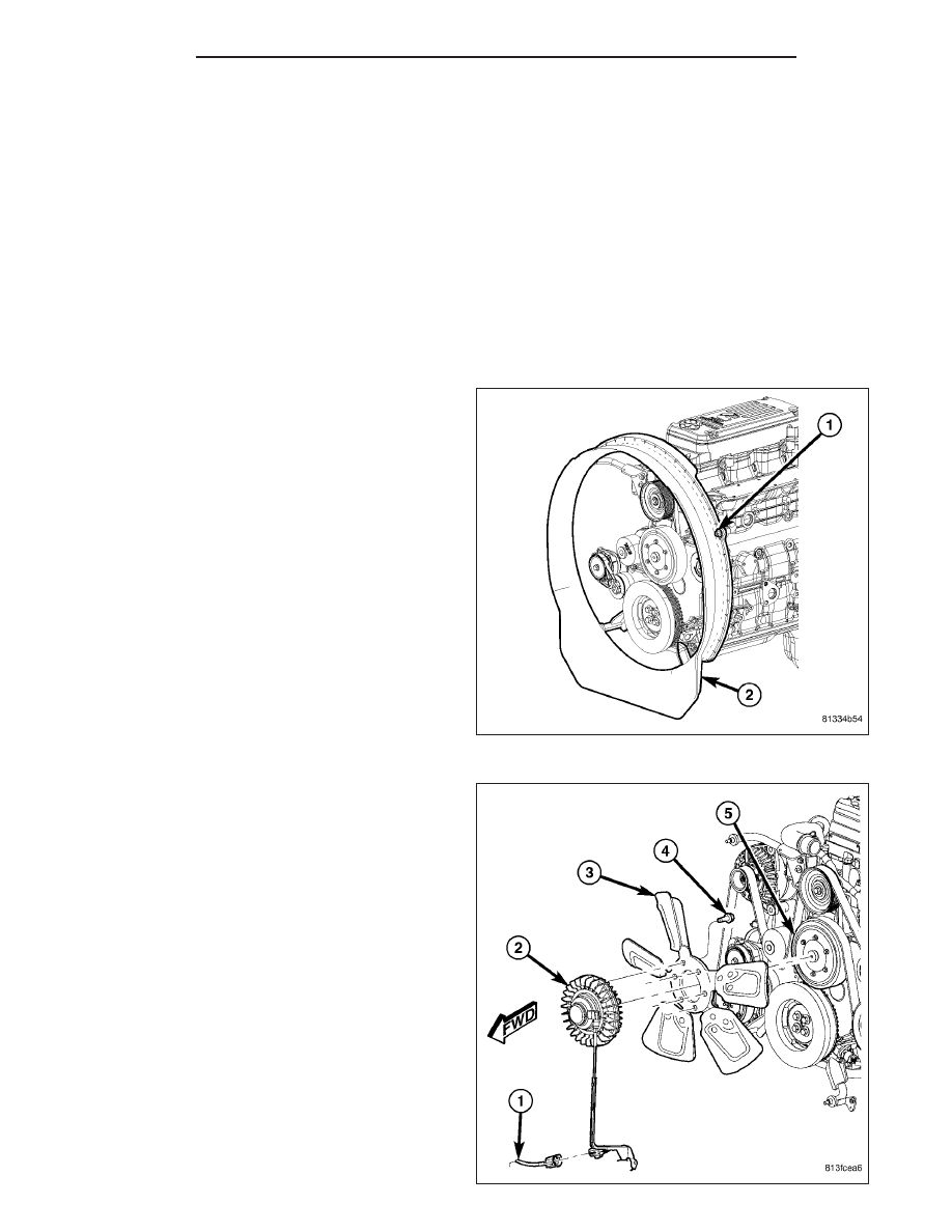
1. Disconnect the battery negative cables.

2. Remove fan shroud-to-engine bracket nuts.

CAUTION: Do not remove the fan pulley bolts.
This pulley is under spring tension.

3. The electronically controlled viscous fan drive/fan

blade assembly is attached (threaded) to the fan
pulley shaft. Remove the fan blade/fan drive
assembly from fan pulley by turning the mounting
nut

counterclockwise

(as

viewed

from

front).

Threads on the viscous fan drive are RIGHT-
HAND. 
A 36 mm fan wrench can be used. Place a
bar or screwdriver between the fan pulley bolts to
prevent pulley from rotating.

4. Disconnect electronically controlled fan clutch con-

nector at lower fan shroud bracket.

5. Remove fan drive wire harness-to-lower fan shroud

bracket mounting bolt.

6. Remove fan drive wire harness support from fan

shroud.

NOTE: It may be necessary to loosen the top two
fan shroud brackets. Removal of the engine
mounted fan shroud brackets is not necessary
unless removing or installing the engine.

7 - 74

ENGINE

DR/DH

7. Collapse fan shroud toward front of vehicle and remove fan drive/fan blade and fan shroud as an assembly.

8. Remove the six fan blade-to-viscous fan drive mounting bolts.

9. Inspect the fan for cracked, chipped or damaged fan blades.

INSTALLATION

3.7L/4.7L/5.7L ENGINE

NOTE: Viscous Fan Drive Fluid Pump Out Require-
ment: After installing a new viscous fan drive,
bring the engine speed up to approximately 2000
rpm and hold for approximately two minutes. This
will ensure proper fluid distribution within the
drive.

1. Install fan blade assembly to the viscous fan drive.

Tighten the bolts to 24 N·m (18 ft. lbs.) torque.

2. Position the fan shroud and the fan blade/viscous

fan drive assembly to the vehicle as a complete
unit.

3. Install the fan shroud.

4. Using Special Tool 6958, install the fan blade/vis-

cous fan drive assembly to the water pump shaft.
Tighten mounting nut to 50 N·m (37 ft. lbs.).

5.

Install the coolant reserve/overflow container to

the fan shroud.

6. Connect the negative battery cable.

5.9L DIESEL ENGINE

NOTE: Viscous Fan Drive Fluid Pump Out Require-
ment: After installing a new viscous fan drive,
bring the engine speed up to approximately 2000
rpm and hold for approximately two minutes. This
will ensure proper fluid distribution within the
drive.

1. Install fan blade assembly to electrically controlled

viscous fan drive. Tighten mounting bolts to 24 N·m
(18 ft. lbs.) torque.

DR/DH

ENGINE

7 - 75

2. Loosen both upper engine mounted fan shroud

brackets.

3. Make sure lower engine mounted fan shroud

bracket nuts are tightened to 24 N·m (18 ft. lbs.).

4. Position fan/fan drive assembly inside fan shroud

and lower into position.

5. Install the viscous fan drive assembly onto fan pul-

ley hub shaft. Tighten mounting nut to 115 N·m (85
ft. lbs.) torque.

6. Install fan drive wir harness support to fan shroud.

7. Install the fan drive wiring harness bracket onto the

lower shroud bracket. Tighten nut to 24 N·m (18 ft.
lbs.).

8. Connect fan drive wire harness.

9. Install fan shroud to upper engine fan shroud

brackets. Tighten nut finger tight.

10. Tighten upper engine fan shroud bracket bolts to

24 NM (18 ft. lbs).

11. Tighten four fan shroud bracket nuts to 24 NM (18 ft. lbs.).

12. Make sure of fan tip clearance all the way around inside of fan shroud.

13. Connect the battery negative cables.

RADIATOR

DESCRIPTION

The radiator is a aluminum cross-flow design with hor-
izontal tubes through the radiator core and vertical
plastic side tanks.

This radiator does not contain an internal transmission
oil cooler.

OPERATION

The radiator supplies sufficient heat transfer using the cooling fins interlaced between the horizontal tubes in the
radiator core to cool the engine.

7 - 76

ENGINE

DR/DH

DIAGNOSIS AND TESTING

RADIATOR COOLANT FLOW

Use the following procedure to determine if coolant is flowing through the cooling system.

1. Idle engine until operating temperature is reached. If the upper radiator hose is warm to the touch, the thermostat

is opening and coolant is flowing to the radiator.

WARNING: HOT, PRESSURIZED COOLANT CAN CAUSE INJURY BY SCALDING. USING A RAG TO COVER
THE RADIATOR PRESSURE CAP, OPEN RADIATOR CAP SLOWLY TO THE FIRST STOP. THIS WILL ALLOW
ANY BUILT-UP PRESSURE TO VENT TO THE RESERVE/OVERFLOW TANK. AFTER PRESSURE BUILD-UP
HAS BEEN RELEASED, REMOVE CAP FROM FILLER NECK.

2. Drain a small amount of coolant from the radiator until the ends of the radiator tubes are visible through the filler

neck. Idle the engine at normal operating temperature. If coolant is flowing past the exposed tubes, the coolant
is circulating.

REMOVAL

3.7L/4.7L/5.7L ENGINE

1. Disconnect battery negative cables.

WARNING: DO NOT REMOVE THE CYLINDER
BLOCK DRAIN PLUGS OR LOOSEN THE RADIA-
TOR DRAINCOCK WITH THE SYSTEM HOT AND
UNDER PRESSURE. SERIOUS BURNS FROM THE
COOLANT CAN OCCUR.

2. Drain the cooling system (Refer to 7 - COOLING -

STANDARD PROCEDURE).

WARNING: CONSTANT TENSION HOSE CLAMPS
ARE USED ON MOST COOLING SYSTEM HOSES.
WHEN REMOVING OR INSTALLING, USE ONLY
TOOLS DESIGNED FOR SERVICING THIS TYPE OF
CLAMP. ALWAYS WEAR SAFETY GLASSES WHEN
SERVICING CONSTANT TENSION CLAMPS.

CAUTION: A number or letter is stamped into the
tongue of constant tension clamps. If replacement
is necessary, use only an original equipment
clamp with a matching number or letter and the
correct width.

DR/DH

ENGINE

7 - 77


Content   ..  240  241  242  243   ..