Dodge Ram Truck 1500-2500-3500. Manual - part 220
9. Subtract each reading from the one 180° opposite
to determine runout and direction. Bore runout
example:
•
0.000 – (–0.007) = 0.007 in.
•
+0.002 – (–0.010) = 0.012 in.
•
+0.004 – (–0.005) = 0.009 in.
•
–0.001 – (+0.001) = –0.002 in.
In this example the largest or total indicator reading
(TIR) difference is 0.012 inch. This means the housing
bore is offset from the crankshaft centerline by 0.006
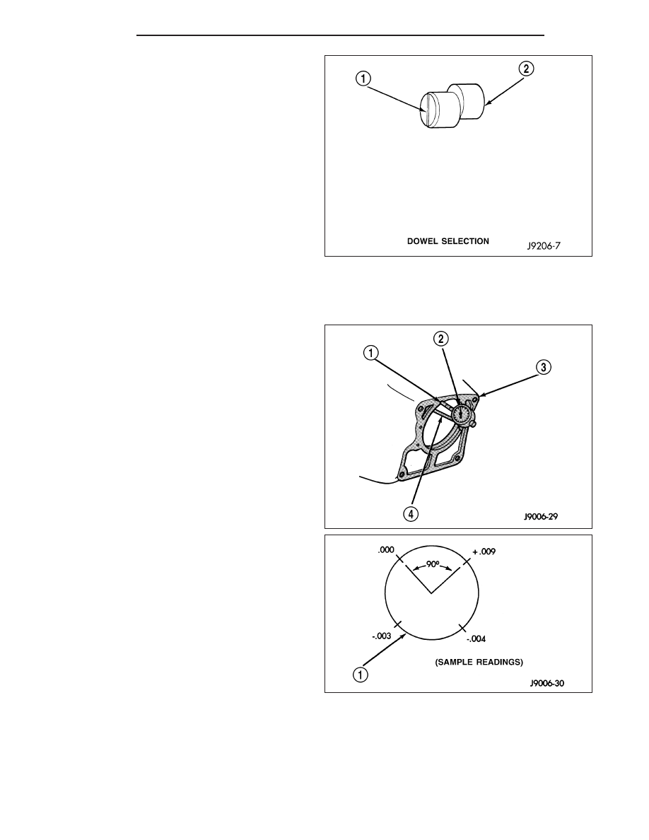
in. which is 1/2 of 0.012 inch. The dowels (2) needed
to correct this have an offset of 0.007 in.
Remove housing and install dowels with the slotted
side facing out so they can be turned with a screw-
driver. Then install the housing and mount the dial
indicator and check bore runout again. Rotate the dowels until the TIR is less than 0.010 inch.
Clutch Housing Face Runout
1. Position dial indicator (2) towards the housing face
with indicator plunger (1) on the rim of the housing
bore.
2. Rotate crankshaft until indicator plunger is at the
10 O’clock position and zero the dial indicator.
3. Measure and record face runout (1) readings at
four points 90° apart. Take measurement at least
twice for accuracy.
4. Subtract lowest reading from highest to determine
total runout. If low reading was minus 0.004 in.
and highest reading was plus 0.009 in. the total
runout is 0.013 inch.
NOTE: Maximum acceptable face runout is 0.010
inch.
To correct this example the shims needed between
the clutch housing and transmission are:
•
0.009 in. at the 0.000 corner
•
0.012 in. at the –0.003 corner
•
0.013 in. at the –0.004 corner
After installing the clutch assembly and housing, tighten the housing bolts nearest the alignment dowels first.
6 - 12
CLUTCH
DR/DH