Content .. 2072 2073 2074 2075 ..
Dodge Ram Truck 1500-2500-3500. Manual - part 2074
NOTE: The protective cap helps aid in service port sealing and helps protects the refrigerant system from
contamination. Remember to always reinstall the protective cap onto the service port when refrigerant sys-
tem service is complete.
6. Install the protective cap (1) onto the service port.
COUPLER-REFRIGERANT LINE
DESCRIPTION
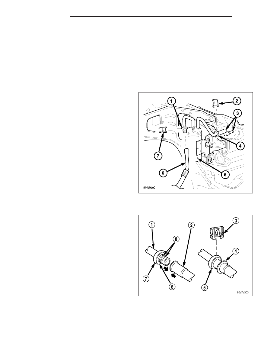
Spring-lock type refrigerant line couplers (1 and 4) are
used to connect the A/C suction line (6) to the A/C
accumulator (5) and, the A/C accumulator and the A/C
liquid line to the A/C evaporator tubes (3). Secondary
retaining clips (2 and 7) are installed over the con-
nected couplers for added protection.
The spring-lock refrigerant line couplers require spe-
cial disconnect tools for disengaging the two coupler
halves.
OPERATION
The spring-lock type refrigerant line coupler is held
together by a garter spring (6) inside a circular cage
(7) on the male half of the fitting (1). When the two
coupler halves are connected, the flared end of the
female fitting (2) slips behind the garter spring inside
the cage on the male fitting. The garter spring and
cage prevent the flared end of the female fitting from
pulling out of the cage. Some applications use a con-
nection indicator ring (4) to help indicate when the two
coupler halves are fully connected.
Two O-rings (8) are used to seal the coupler connec-
tions. These O-rings are compatible with R-134a
refrigerant and must be replaced with O-rings made of
the same material.
A secondary retaining clip (3) is installed over the con-
nected coupler (5) for added protection.
24 - 296
PLUMBING
DR/DH