Dodge Ram Truck 1500-2500-3500. Manual - part 2054


  Index      Dodge     Dodge Ram Truck 1500-2500-3500 - service repair manual 2005 year


Search            


Content   ..  2052  2053  2054  2055   ..


Dodge Ram Truck 1500-2500-3500. Manual - part 2054


6. Remove the clutch plate and shims.

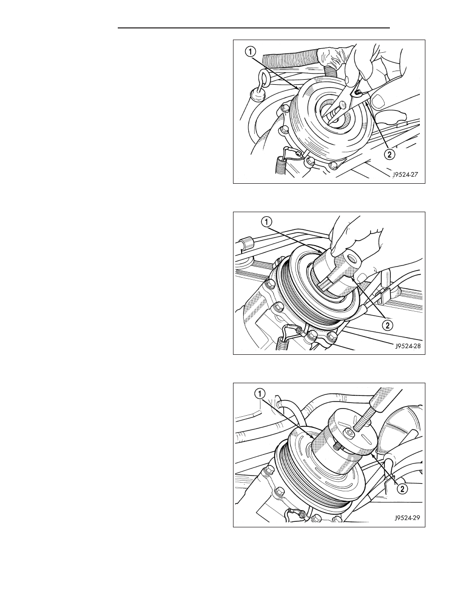
7. Using snap ring pliers (Special Tool C-4574 or

equivalent) (2), remove the snap ring that secures
the pulley and bearing assembly (1).

8. Install the lip of the pulley and bearing puller (Spe-

cial Tool C-6141-1 or equivalent) (1) into the snap
ring groove of the pulley and bearing assembly and
install the shaft protector (Special Tool C-6141-2 or
equivalent) (2).

CAUTION: Do not apply excessive force to the end
of the compressor shaft with the puller center bolt
or damage to the shaft may occur.

9. Install the puller through-bolts (Special Tool C-6461

or equivalent) through the puller flange (2) and into
the puller jaws (1). Turn the puller center bolt clock-
wise until the pulley and bearing assembly is free.

24 - 216

CONTROLS

DR/DH

10. Remove the screw and retainer (3) from the wire

harness lead (2) of the clutch field coil (1).

11. Using snap ring pliers (Special Tool C-4574 or

equivalent) (2), remove the snap ring that secures
the clutch field coil (1) and remove the field coil.

DENSO A/C COMPRESSOR

NOTE: The A/C compressor clutch can be serviced in the vehicle. The refrigerant system can remain fully-
charged during compressor clutch, pulley and bearing assembly, or coil replacement.

DR/DH

CONTROLS

24 - 217

1. Disconnect and isolate the negative battery cable.

2. Remove the accessory drive belt (Refer to 7 -

COOLING/ACCESSORY

DRIVE/BELTS-DRIVE

-

REMOVAL).

3. Disconnect the engine wire harness connector for

the A/C compressor clutch coil from the clutch field
coil wire harness connector on the top of the A/C
compressor.

4. Remove the bolts that secure the A/C compressor

to the engine and support the A/C compressor.

5. Remove the compressor shaft bolt (1). A band-type

oil filter wrench or a strap wrench may be used to
secure the clutch plate (2) during bolt removal.

CAUTION: Do not pry between the clutch plate and
the pulley and bearing assembly to remove the
clutch plate from the compressor shaft as this
may damage the clutch plate.

NOTE: Use care not to lose any clutch shim(s)
during removal of the clutch plate, as they may be
reused during the clutch plate installation process.

6. Tap the clutch plate (2) lightly with a plastic mallet

to release it from the splines on the compressor
shaft (1). Remove the clutch plate and shim(s) (3)
from the compressor shaft.

24 - 218

CONTROLS

DR/DH

7. Using snap ring pliers (Special Tool C-4574 or

equivalent) (2), remove the external snap ring (1)
that secures the pulley and bearing assembly (3) to
the front cover of the A/C compressor, then slide
the pulley and bearing assembly off of the A/C
compressor.

8. Remove the screw that secures the clutch coil pig-

tail wire connector bracket and ground clip to the
top of the compressor housing (3).

9. Using snap ring pliers (Special Tool C-4574 or

equivalent) (1), remove the external snap ring (4)
that secures the clutch field coil (2) to the front
cover of the compressor housing, then slide the
clutch field coil off of the A/C compressor.

DR/DH

CONTROLS

24 - 219


Content   ..  2052  2053  2054  2055   ..