Content .. 2050 2051 2052 2053 ..
Dodge Ram Truck 1500-2500-3500. Manual - part 2052
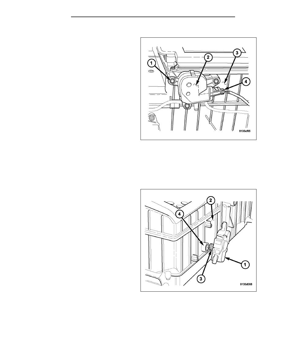
DEFROST DOOR ACTUATOR
1. Disconnect and isolate the negative battery cable.
2. Remove the instrument panel from the vehicle
(Refer to 23 - BODY/INSTRUMENT PANEL/IN-
STRUMENT PANEL ASSEMBLY - REMOVAL).
3. Remove the screws (1) that secure the defrost
door actuator (2) to the back of the HVAC housing
(3).
4. Remove the defrost door actuator from the HVAC
housing and disconnect the HVAC wire harness
connector (4) from the actuator.
5. Remove the defrost door actuator from the vehicle.
INSTALLATION
NOTE: The heating-A/C system is equipped with two mode door actuators, one for the panel/floor-air door
and one for the defrost-air door.
PANEL/FLOOR DOOR ACTUATOR
1. Install the panel/floor door actuator (1) onto the
back of the HVAC housing (2). If necessary, rotate
the actuator slightly to align the splines on the
actuator output shaft (3) with those on the panel/
floor door actuator coupler (4).
24 - 208
CONTROLS
DR/DH