Dodge Ram Truck 1500-2500-3500. Manual - part 1943


  Index      Dodge     Dodge Ram Truck 1500-2500-3500 - service repair manual 2005 year


Search            


Content   ..  1941  1942  1943  1944   ..


Dodge Ram Truck 1500-2500-3500. Manual - part 1943


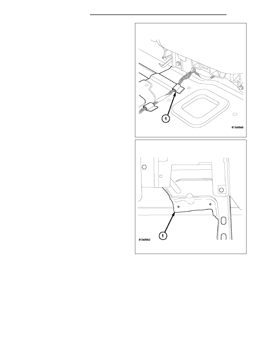
4. The ACM wire harness (1) runs rearward along the

left side of the tunnel under the carpet. Rub your
hand along the carpet in the area of the bottom of
the ACM cover and feel for the harness. If the har-
ness can be felt, it may be pushing the ACM cover
upward and into the cup holder. If this is happening
it may be necessary to reroute the harness or
remove carpet padding from the area.

5. Roll the carpet back and make sure that there are

no plastic retainers in the area that could cause the
interference. If a retainer is present remove it.
Make sure that the harness is not sitting on a
raised portion of the floor. If it is, reroute the har-
ness to a lower area on the floor. Remove the any
carpet padding from the area where the harness
contacts the carpet to gain additional clearance.
This should provide the clearance needed. and
complete the repair.

6. Remove the cup holder.

7. Operate the cup holder out of the vehicle. If the

cup holder still binds it must be replaced. If it oper-
ates freely, inspect the metal bracket (1) where the
cup holder fasteners attach as shown. If the
bracket is bent, it could cause the cup holder to
twist or distort when the screws are installed.
Straighten the bracket and install the cup holder. If
the cup holder operates freely the repair is com-
plete. if the cup holder still binds, it must be
replaced.

23 - 126

INSTRUMENT PANEL

DR/DH

INSTALLATION

NOTE: A storage bin replaces the cup holder in
the instrument panel when the vehicle is equipped
with a floor console.

1. Position the cup holder (2) into the instrument

panel.

2. Install the four screws (1) that secure the cup

holder to the instrument panel. Tighten the screws
to 2.2 N·m (20 in. lbs.).

3. Open the cup holder (1) and install the two screws

(2) that secure the cup holder to the instrument
panel. Tighten the screws to 2.2 N·m (20 in. lbs.).

4. Install the center bezel (Refer to 23 - BODY/IN-

STRUMENT PANEL/INSTRUMENT PANEL CEN-
TER BEZEL - INSTALLATION).

5. Install the airbag control module cover (Refer to 8 -

ELECTRICAL/RESTRAINTS/COVER-AIRBAG
CONTROL MODULE - INSTALLATION).

DR/DH

INSTRUMENT PANEL

23 - 127

GLOVE BOX

REMOVAL

1. Open the glove box (1).

2. Release the two glove box stops (2) and lower the

glove box downward past the stops.

3. Disengage the glove box hinges from the instru-

ment panel and remove the glove box.

INSTALLATION

1. Engage the hinges of the glove box (1) to the

instrument panel.

2. Press downward on the back edge of the glove box

bin and raise the glove box past the two stops (2).

3. Close the glove box.

23 - 128

INSTRUMENT PANEL

DR/DH

GLOVE BOX LATCH

REMOVAL

1. Remove the glove box and place it on a workbench

(Refer

to

23

-

BODY/INSTRUMENT

PANEL/

GLOVE BOX - REMOVAL).

2. Remove the 15 screws (1) that secure the glove

box bin (2) and the inner glove box door panel (3)
to the outer glove box door panel (4).

3. Remove the glove box bin and the inner glove box

door panel from the outer glove box door panel.

4. Remove the two screws (1) that secure the glove

box latch (2) to the outer glove box door panel (3)
and remove the latch.

DR/DH

INSTRUMENT PANEL

23 - 129


Content   ..  1941  1942  1943  1944   ..