Content .. 1930 1931 1932 1933 ..
Dodge Ram Truck 1500-2500-3500. Manual - part 1932
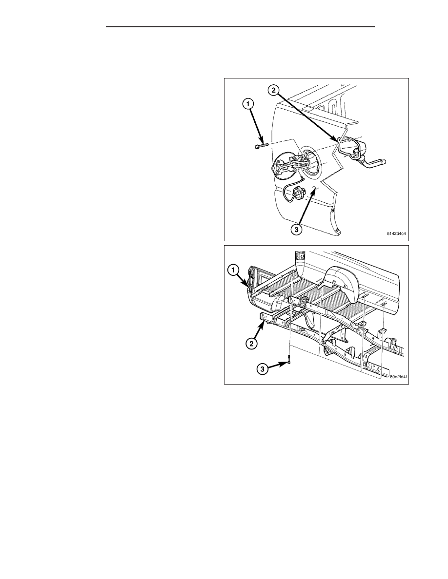
CARGO BOX
REMOVAL
NOTE: Long cargo box shown in illustration. Short
cargo box similar.
1. Remove the screws (1) that secure the fuel filler (2)
to the cargo box (3).
2. Remove the fuel filler from the cargo box and posi-
tion it out of the way.
3. If necessary, remove the fuel filler door from the
cargo box (Refer to 23 - BODY/EXTERIOR/FUEL
FILL DOOR - REMOVAL).
4. Disconnect the tail lamp wire harness from the
underbody wire harness (Refer to 8 - ELECTRI-
CAL/CONNECTOR/GROUND/SPLICE
LOCATION
- DESCRIPTION).
5. If necessary, remove the tail lamp units and wire
harness from the cargo box (Refer to 8 - ELECTRI-
CAL/LAMPS/LIGHTING - EXTERIOR/TAIL LAMP
UNIT - REMOVAL).
6. If necessary, remove the tailgate (Refer to 23 -
BODY/TAILGATE/TAILGATE - REMOVAL).
7. If necessary, remove the rear bumper (Refer to 13
-
FRAME
&
BUMPERS/BUMPERS/REAR
BUMPER - REMOVAL).
8. Remove the bolts (3) that secure the cargo box (1)
to the frame (2) (six short box, eight long box) and
remove the cargo box.
23 - 82
EXTERIOR
DR/DH