Content .. 1799 1800 1801 1802 ..
Dodge Ram Truck 1500-2500-3500. Manual - part 1801
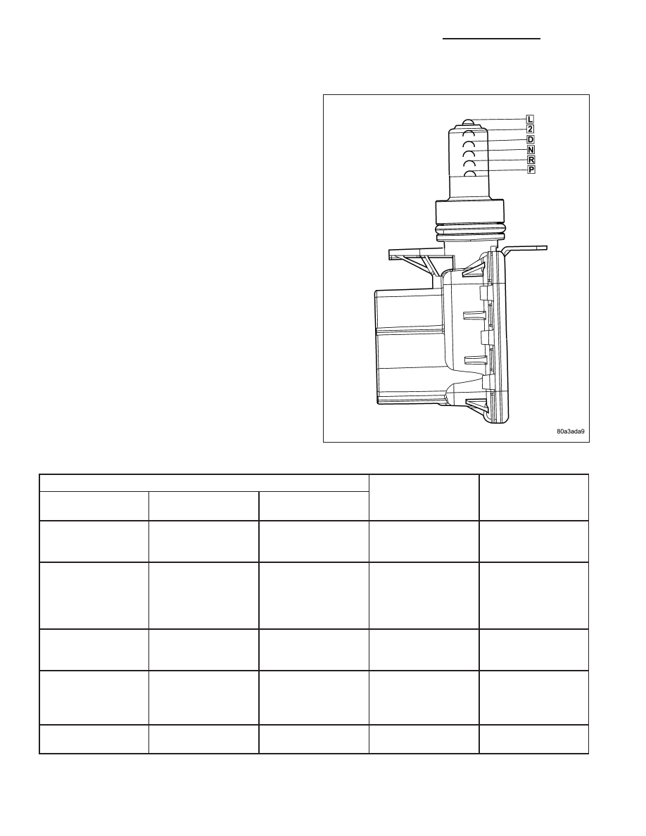
OPERATION
As the switch moves through its linear motion contacts
slide across a circuit board which changes the resis-
tance between the range sensing pins of the switch. A
power supply on the instrument cluster provides a reg-
ulated voltage signal to the switch. The return signal is
decoded by the cluster, which then controls the
PRNDL display to correspond with the correct trans-
mission range. A bus message of transmission range
is also sent by the cluster. In REVERSE range a sec-
ond contact set closes the circuit providing power to
the reverse lamps.
Indicated Gear Position
Transmission
Status
Column Shifter
Position
Mechanical State
Electronic Display
(Ignition Unlocked)
Electronic Display
(Ignition On)
P
P
P
Vehicle is in PARK
with the pawl
engaged.
In the PARK gate.
R
The PARK pawl is
disengaged and the
vehicle is free to
roll, but REVERSE
is not engaged.
Between the PARK
and REVERSE
gates.
R
R
R
The transmission is
hydraulically in
REVERSE.
In the REVERSE
gate.
N
The transmission is
transitioning
between REVERSE
and NEUTRAL.
Between the
REVERSE and
NEUTRAL gates.
N
N
N
The vehicle is in
NEUTRAL.
In the NEUTRAL
gate.
21 - 1136
AUTOMATIC TRANSMISSION - 48RE - SERVICE INFORMATION
DR/DH