Dodge Ram Truck 1500-2500-3500. Manual - part 1800


  Index      Dodge     Dodge Ram Truck 1500-2500-3500 - service repair manual 2005 year


Search            


Content   ..  1798  1799  1800  1801   ..


Dodge Ram Truck 1500-2500-3500. Manual - part 1800


INSTALLATION

Check converter hub and drive notches for sharp
edges, burrs, scratches, or nicks. Polish the hub and
notches with 320/400 grit paper or crocus cloth if nec-
essary. The hub must be smooth to avoid damaging
the pump seal at installation.

1. Lubricate oil pump seal lip with transmission fluid.

2. Place torque converter in position on transmission.

CAUTION: Do not damage oil pump seal or bush-
ing while inserting torque converter into the front
of the transmission.

3. Align torque converter to oil pump seal opening.

4. Insert torque converter hub into oil pump.

5. While pushing torque converter inward, rotate con-

verter until converter is fully seated in the oil pump
gears.

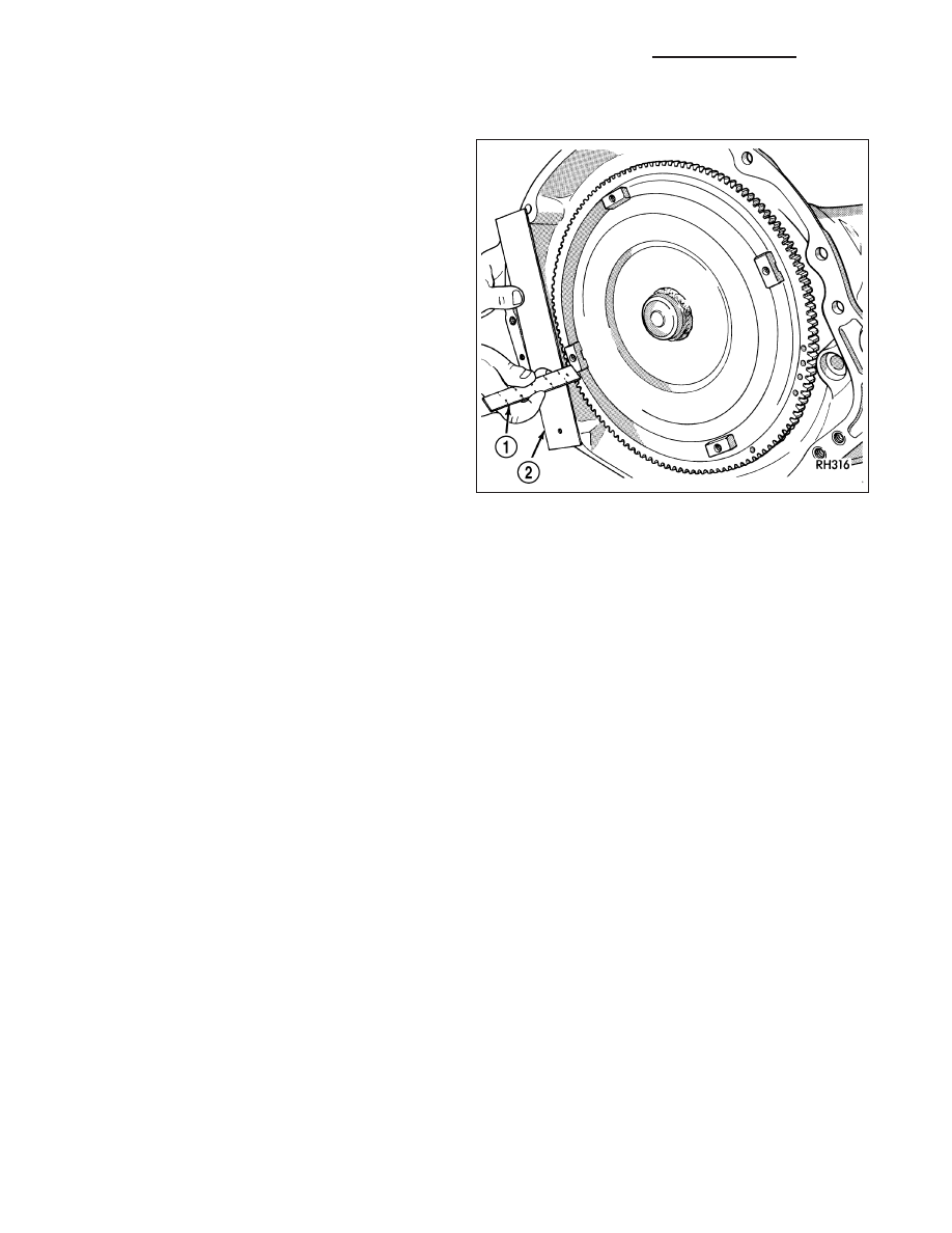
6. Check converter seating with a scale (1) and

straightedge (2). Surface of converter lugs should
be 19mm (0.75 in.) to the rear of the straightedge when converter is fully seated.

7. If necessary, temporarily secure converter with C-clamp attached to the converter housing.

8. Install the transmission in the vehicle.

9. Fill the transmission with the recommended fluid.

VALVE-TORQUE CONVERTER DRAINBACK

DESCRIPTION

GAS ENGINES

The drainback valve is located in the transmission cooler outlet (pressure) line.

DIESEL ENGINE

The converter drainback check valve is located in the in the TOC pressure - supply line, between the engine
mounted TOC and the air to oil TOC.

OPERATION

GAS ENGINES

The valve prevents fluid from draining from the converter into the cooler and lines when the vehicle is shut down for
lengthy periods. Production valves have a hose nipple at one end, while the opposite end is threaded for a flare
fitting. All valves have an arrow (or similar mark) to indicate direction of flow through the valve.

DIESEL ENGINE

The valve prevents fluid from draining from the converter into the cooler and lines when the vehicle is shut down for
lengthy periods. Production valves have pipe thread on one end, while the opposite end is threaded for a flare
fitting, and are threaded into the oil cooler mounted on the side of the engine. All valves have an arrow (or similar
mark) to indicate direction of flow through the valve.

21 - 1132

AUTOMATIC TRANSMISSION - 48RE - SERVICE INFORMATION

DR/DH

STANDARD PROCEDURE

GAS ENGINES

The converter drainback check valve is located in the cooler outlet (pressure) line near the radiator tank. The valve
prevents fluid drainback when the vehicle is parked for lengthy periods. The valve check ball is spring loaded and
has an opening pressure of approximately 2 psi.

The valve is serviced as an assembly; it is not repairable. Do not clean the valve if restricted, or contaminated by
sludge, or debris. If the valve fails, or if a transmission malfunction occurs that generates significant amounts of
sludge and/or clutch particles and metal shavings, the valve must be replaced.

If the valve is restricted, installed backwards, or in the wrong line, it will cause an transmission overheating condition
and possible transmission failure.

CAUTION: The drainback valve is a one-way flow device. It must be properly oriented in terms of flow direc-
tion for the cooler to function properly. The valve must be installed in the pressure line. Otherwise flow will
be blocked and would cause an transmission overheating condition and eventual transmission failure.

DIESEL ENGINE

The converter drainback check valve is located in the in the TOC pressure - supply line, between the engine
mounted transmission oil cooler and the air to oil transmission oil cooler. The valve prevents fluid drainback when
the vehicle is parked for lengthy periods. The valve check ball is spring loaded and has an opening pressure of
approximately 2 psi.

The valve is serviced as an assembly; it is not repairable. Do not clean the valve if restricted, or contaminated by
sludge, or debris. If the valve fails, or if a transmission malfunction occurs that generates significant amounts of
sludge and/or clutch particles and metal shavings, the valve must be replaced.

If the valve is restricted, installed backwards, or in the wrong line, it will cause an transmission overheating condition
and possible transmission failure.

CAUTION: The drainback valve is a one-way flow device. It must be properly oriented in terms of flow direc-
tion for the cooler to function properly. The valve must be installed in the pressure line. Otherwise flow will
be blocked and would cause an transmissionn overheating condition and eventual transmission failure.

SWITCH-TOW/HAUL OVERDRIVE

DESCRIPTION

The tow/haul overdrive OFF (control) switch is located
in the shift lever arm. The switch is a momentary con-
tact device that signals the PCM to toggle current sta-
tus of the overdrive function.

DR/DH

AUTOMATIC TRANSMISSION - 48RE - SERVICE INFORMATION

21 - 1133

OPERATION

At key-on, overdrive operation is allowed. Pressing the switch once causes the tow/haul overdrive OFF mode to be
entered and the Tow/Haul lamp to be illuminated. Pressing the switch a second time causes normal overdrive oper-
ation to be restored and the tow/haul lamp to be turned off. The tow/haul overdrive OFF mode defaults to ON after
the ignition switch is cycled OFF and ON. The normal position for the control switch is the ON position. The switch
must be in this position to energize the solenoid and allow a 3-4 upshift. The control switch indicator light illuminates
only when the tow/haul overdrive switch is turned to the OFF position, or when illuminated by the transmission
control module.

DIAGNOSIS AND TESTING - OVERDRIVE ELECTRICAL CONTROLS

The tow/haul overdrive off switch, valve body solenoid, case connectors and related wiring can all be tested with a
12 volt test lamp or a volt/ohmmeter. Check continuity of each component when diagnosis indicates this is neces-
sary.

Switch and solenoid continuity should be checked whenever the transmission fails to shift into fourth gear range.

REMOVAL

1. Using a plastic trim tool, remove the tow/haul over-

drive off switch retainer (2) from the shift lever (1).

2. Pull the switch (2) outwards to release it from the

connector in the lever (1)

21 - 1134

AUTOMATIC TRANSMISSION - 48RE - SERVICE INFORMATION

DR/DH

INSTALLATION

NOTE: There is enough slack in the wire to pull out the connector from the lever.

1. Pull the connector (2) out of the lever (1) just

enough to grasp it.

CAUTION: Be careful not to bend the pins on the
tow/haul overdrive off switch. Use care when
installing the switch, as it is not indexed, and can
be accidentally installed incorrectly.

2. Install the tow/haul overdrive off switch (3) into the

connector (2)

3. Push the tow/haul overdrive off switch (3) and wir-

ing into the shift lever (1).

4. Install the tow/haul overdrive off switch retainer

onto the shift lever.

SENSOR-TRANSMISSION RANGE

DESCRIPTION

The Transmission Range Sensor (TRS) has 3 primary
functions:

Provide a PARK/NEUTRAL start signal to the
engine controller and the starter relay.

Turn the Back-up lamps on when the transmis-
sion is in REVERSE and the engine (ignition) is
on.

Provide a transmission range signal to the instru-
ment cluster.

The sensor is mounted in the transmission housing
near the valve body, just above the pan rail. It’s in the
same position as the Park/Neutral switch on other
transmissions. The TRS contacts a cammed surface
on the manual valve lever. The cammed surface trans-
lates the rotational motion of the manual lever into the
linear motion of the sensor. The cammed surface on
the manual lever is comprised of two parts controlling
the TRS signal: The insulator portion contacts the
switch poppet when the manual lever is not in PARK
or NEUTRAL. The manual lever itself contacts the
poppet when the lever is in PARK or NEUTRAL; pro-
viding a ground for the signal from the starter relay
and the appropriate engine controller.

DR/DH

AUTOMATIC TRANSMISSION - 48RE - SERVICE INFORMATION

21 - 1135


Content   ..  1798  1799  1800  1801   ..