Dodge Ram Truck 1500-2500-3500. Manual - part 1469


  Index      Dodge     Dodge Ram Truck 1500-2500-3500 - service repair manual 2005 year


Search            


Content   ..  1467  1468  1469  1470   ..


Dodge Ram Truck 1500-2500-3500. Manual - part 1469


8.3L - SRT-10

The IAC motor is inserted into a housing at the front of the intake manifold. The IAC motor and housing are ser-
viced together.

1. Attach electrical connector to IAC motor.

2. Install IAC motor into and housing on manifold. Tighten mounting screws to 4 N·m (35 in. lbs.) torque.

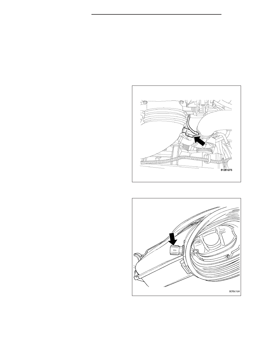
SENSOR - INLET AIR TEMPERATURE

REMOVAL — 8.3L

NOTE: Take care not to damage the thermister pill
when removing the sensor.

1. Remove the battery cover and disconnect the neg-

ative battery cable.

2. Disconnect the electrical connector from the inlet

temperature sensor.

3. Remove sensor from inlet hose.

INSTALLATION

NOTE: Take care not to damage the open ther-
mister pill when installing the sensor.

1. Install sensor , use a little water to aid in insertion

of sensor.

2. Make sure that the rib on the sensor matches up

with the rib on the inlet hose. The thermister pill
should be in direct contact with the inlet air stream.

3. Connect the electrical connector.

4. Connect the negative battery cable and install bat-

tery cover.

14 - 64

FUEL INJECTION - GAS

DR/DH

SENSOR-INTAKE AIR TEMPERATURE

DESCRIPTION

3.7L V-6

The 2-wire Intake Manifold Air Temperature (IAT) sen-
sor (1) is installed in the intake manifold with the sen-
sor element extending into the air stream.

The IAT sensor is a two-wire Negative Thermal Coef-
ficient (NTC) sensor. Meaning, as intake manifold tem-
perature increases, resistance (voltage) in the sensor
decreases. As

temperature

decreases,

resistance

(voltage) in the sensor increases.

4.7L V-8

The 2-wire Intake Manifold Air Temperature (IAT) sen-
sor (3) is installed in the intake manifold with the sen-
sor element extending into the air stream.

The IAT sensor is a two-wire Negative Thermal Coef-
ficient (NTC) sensor. Meaning, as intake manifold tem-
perature increases, resistance (voltage) in the sensor
decreases. As

temperature

decreases,

resistance

(voltage) in the sensor increases.

DR/DH

FUEL INJECTION - GAS

14 - 65

5.7L V-8

The 2-wire Intake Manifold Air Temperature (IAT) sen-
sor is installed in the intake manifold (2) with the sen-
sor element extending into the air stream.

The IAT sensor is a two-wire Negative Thermal Coef-
ficient (NTC) sensor. Meaning, as intake manifold tem-
perature increases, resistance (voltage) in the sensor
decreases. As

temperature

decreases,

resistance

(voltage) in the sensor increases.

OPERATION

The IAT sensor provides an input voltage to the Powertrain Control Module (PCM) indicating the density of the air
entering the intake manifold based upon intake manifold temperature. At key-on, a 5–volt power circuit is supplied
to the sensor from the PCM. The sensor is grounded at the PCM through a low-noise, sensor-return circuit.

The PCM uses this input to calculate the following:

Injector pulse-width

Adjustment of spark timing (to help prevent spark knock with high intake manifold air-charge temperatures)

The resistance values of the IAT sensor is the same as for the Engine Coolant Temperature (ECT) sensor.

14 - 66

FUEL INJECTION - GAS

DR/DH

REMOVAL

3.7L V-6

The intake manifold air temperature (IAT) sensor is
installed into the left side of intake manifold plenum.

1. Disconnect electrical connector from IAT sensor.

2. Clean dirt from intake manifold at sensor base.

3. Gently lift on small plastic release tab (3) and

rotate sensor about 1/4 turn counter-clockwise for
removal.

4. Check condition of sensor o-ring.

DR/DH

FUEL INJECTION - GAS

14 - 67


Content   ..  1467  1468  1469  1470   ..