Dodge Ram Truck 1500-2500-3500. Manual - part 1419


  Index      Dodge     Dodge Ram Truck 1500-2500-3500 - service repair manual 2005 year


Search            


Content   ..  1417  1418  1419  1420   ..


Dodge Ram Truck 1500-2500-3500. Manual - part 1419
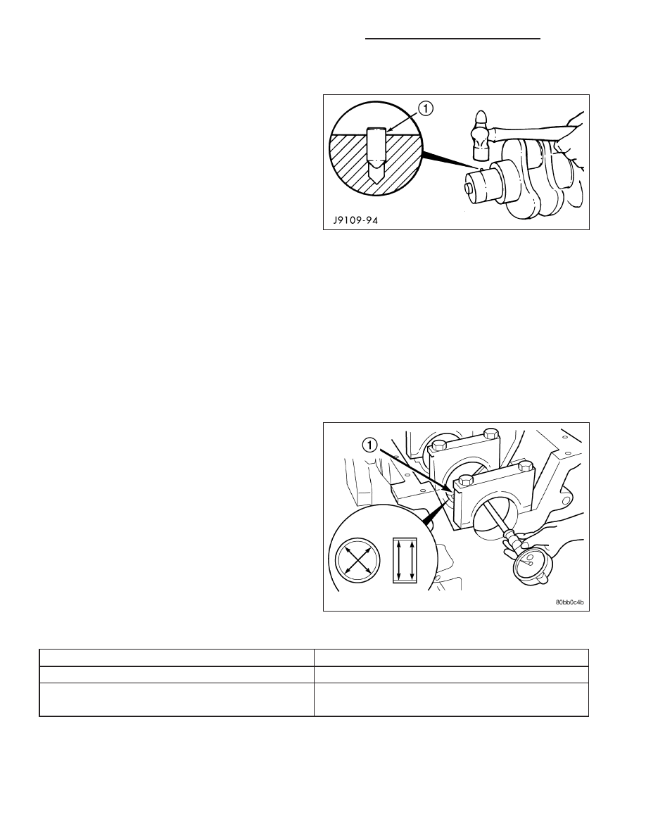


INSTALLATION - GEAR

1. Remove all burrs and make sure the gear surface

on the end of the crankshaft is smooth.

2. If removed, install a new alignment pin. Drive the

pin in using a ball- peen hammer, leaving it pro-
truding 1.0 mm (0.039 inch) to 1.5 mm (0.059 inch)
above the crankshaft.

WARNING: WEAR PROTECTIVE GLOVES TO PRE-
VENT INJURY.

CAUTION: DO NOT heat the gear longer than 45
minutes.

3. Heat the crankshaft gear for 45 minutes at a temperature of 149°C (300°F). Do not use torch, gear failure will

occur.

4. Apply a thin coat of lubricant to the nose of the crankshaft.

5. Position the gear with the timing mark out and install it on the crankshaft using the alignment pin. Make sure the

gear contacts the shoulder.

BEARINGS - CRANKSHAFT MAIN

STANDARD PROCEDURE - MAIN BEARING CLEARANCE

MAIN BEARING BORE DIAMETER CHART

ITEM

MAIN BEARING BORE DIAMETER (MAXIMUM)

BEARINGS INSTALLED

83.106 mm (3.2719 in.)

BEARINGS REMOVED

Min 87.983 mm (3.4639 in.)

Max. 88.019 mm (3.4653 in.)

Inspect the main bearing bores for damage or abnormal wear.

1. Remove bearings and measure main bearing bore diameter after torquing main bearing cap bolts to 176 Nm

(130 ft. lbs.).

2. Install the crankshaft main bearings and measure main bearing bore diameter with the main bolts tightened to

176 N·m (130 ft. lbs.) torque.

9 - 2598

ENGINE - 5.9L DIESEL - SERVICE INFORMATION

DR/DH

CRANKSHAFT MAIN JOURNAL DIAMETER CHART

ITEM

SPECIFICATION

Minimum diameter

82.962 mm (3.2662 in.)

Maximum diameter

83.013 mm (3.2682 in.)

Maximum out of roundness

0.050 mm (.002 in.)

Maximum taper

0.013 mm (.0005 in.)

Thrust distance (at No.6 position)

Min. 0.065 mm (.003 in.)

Max. 0.432 mm (.017 in.)

3. Measure the diameter of the main journal at the locations shown. Calculate the average diameter for each side

of the journal.

4. Calculate the main bearing journal to bearing clearance. Maximum clearance is 0.119 mm (0.00475 inch). If the

crankshaft journal is within limits, replace the main bearings. If not within specifications, grind the crankshaft to
next size and use oversize bearings.

5. Measure thrust distance at the No.6 position.

SEAL - CRANKSHAFT OIL - FRONT

REMOVAL

1. Disconnect both battery negative cables.

2. Raise vehicle on hoist.

3. Partially drain engine coolant into container suitable for re-use (Refer to 7 - COOLING - STANDARD PROCE-

DURE).

4. Lower vehicle.

5. Remove radiator upper hose.

6. Disconnect coolant recovery bottle hose from radiator filler neck.

7. Disconnect windshield washer pump supply hose and electrical connections and lift washer bottle off of fan

shroud.

8. Remove viscous fan/drive assembly. (Refer to 7 - COOLING/ENGINE/RADIATOR FAN - REMOVAL).

9. Remove cooling fan shroud and fan assembly from the vehicle.

10. Remove the accessory drive belt (Refer to 7 - COOLING/ACCESSORY DRIVE/DRIVE BELTS - REMOVAL).

11. Remove the cooling fan support/hub from the front of the engine.

12. Raise the vehicle on hoist.

13. Remove the crankshaft damper and speed indicator ring.

DR/DH

ENGINE - 5.9L DIESEL - SERVICE INFORMATION

9 - 2599

14. Remove power steering pump.

15. Remove accessory drive belt tensioner.

16. Remove the gear cover-to-housing bolts and gen-

tly pry the cover away from the housing, taking
care not to mar the gasket surfaces. Remove
crank seal dust shield with cover.

17. Support the cover on a flat work surface with

wooden blocks, and using a suitable punch (1)
and hammer, drive the old seal out of the cover
from the back side of the cover to the front side.

INSTALLATION

CAUTION: The seal lip and the sealing surface on
te crankshaft must be be from all oil residue, to
prevent leaks. The crankshaft and seal surface
must be completely dry when the seal is installed.

1. Clean cover and housing gasket mating surfaces.

Use a suitable scraper and be careful not to dam-
age the gear housing surface. Remove any old
sealer from the oil seal bore. Thoroughly clean the
front seal area of the crankshaft. The seal lip and
the sealing surface on the crankshaft must be free
from all oil residue to prevent seal leaks.

2. Inspect the gear housing and cover for cracks and

replace if necessary. Carefully straighten any bends
or imperfections in the gear cover with a ball-peen
hammer on a flat surface. Inspect the crankshaft
front journal for any grooves or nicks that would
affect the integrity of the new seal.

3. Apply a bead of Mopar

T

Stud & Bearing Mount to

the outside diameter of the seal. Do not lubricate
the inside diameter of the new seal.

4. With the cover supported by wood blocks, install the seal into the rear of the cover using crankshaft seal installer

Special Tool 8281 and driver handle C-4171. Strike the driver handle until the installation tool bottoms out on the
inside of the cover.

CAUTION: Do not distort or damage seal.

9 - 2600

ENGINE - 5.9L DIESEL - SERVICE INFORMATION

DR/DH

5. Install the plastic seal pilot (provided with seal kit)

into the crankshaft seal.

6. Apply a bead of Mopar

T

Silicone Rubber Adhesive

Sealant or equivalent to the gear housing cover
sealing surface.

7. Install the cover to the gear housing, aligning the

seal pilot with the nose of the crankshaft.

8. Install the cover bolts and tighten to 24 N·m (18 ft.

lbs.) torque. Remove pilot tool.

9. Install dust shield over nose of crankshaft.

10. Install the crankshaft damper and speed indicator

ring. Torque the bolts to 40 N·m (30 ft. lbs.). Then
rotate an additional 60°. Use the engine barring
tool to keep the engine from rotating during tightening operation.

11. Install the fan support/hub assembly and torque bolts to 32 N·m (24 ft. lbs.).

12. Install power steering pump.

13. Install accessory drive belt tensioner. Torque bolt to 43 Nm (32 ft.lbs.).

14. Install cooling fan (Refer to 7 - COOLING/ENGINE/RADIATOR FAN - INSTALLATION).

15. Install the accessory drive belt (Refer to 7 - COOLING/ACCESSORY DRIVE/DRIVE BELTS - INSTALLATION).

16. Refill cooling system (Refer to 7 - COOLING - STANDARD PROCEDURE).

17. Connect battery negative cables.

18. Start engine and check for oil leaks.

SEAL - CRANKSHAFT OIL - REAR

REMOVAL

1. Disconnect the battery negative cables.

2. Remove the transmission and transfer case (if

equipped).

3. Remove the clutch cover and disc (if manual trans-

mission equipped) (Refer to 6 - CLUTCH/CLUTCH
DISC - REMOVAL).

4. Remove the flywheel or converter drive plate.

5. FOR LATE BUILDS Remove the flywheel adapter

plate.

6. Drill holes 180° apart into the seal. Be careful not

to contact the drill against the crankshaft.

7. Install #10 sheet metal screws (1) in the drilled

holes and remove the rear seal with a slide ham-
mer (4).

INSTALLATION

CAUTION: The seal lip and the sealing surface on the crankshaft must be free from all oil residue to prevent
seal leaks. The crankshaft and seal surfaces must be completely dry when the seal is installed. Use a soap
and water solution on outside diameter of seal to ease assembly.

1. Clean the crankshaft journal with a suitable solvent and dry with a clean shop towel or compressed air. Wipe the

inside bore of the crankshaft seal retainer with a clean shop towel.

DR/DH

ENGINE - 5.9L DIESEL - SERVICE INFORMATION

9 - 2601


Content   ..  1417  1418  1419  1420   ..