Dodge Ram Truck 1500-2500-3500. Manual - part 1395


  Index      Dodge     Dodge Ram Truck 1500-2500-3500 - service repair manual 2005 year


Search            


Content   ..  1393  1394  1395  1396   ..


Dodge Ram Truck 1500-2500-3500. Manual - part 1395
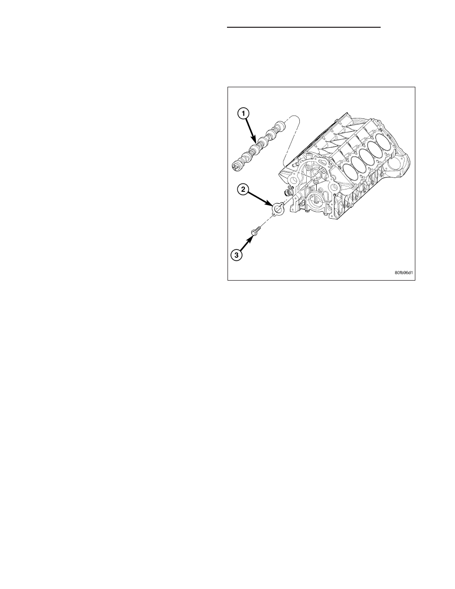


CAMSHAFT

REMOVAL

1. Perform the fuel pressure relief procedure (Refer to

14 - FUEL SYSTEM/FUEL DELIVERY - STAN-
DARD PROCEDURE).

2. Disconnect the negative battery cable.

3. Raise and support the vehicle.

4. Remove the front engine shield.

5. Drain the cooling system

6. Drain the power steering fluid.

7. Remove the oil pan (Refer to 9 - ENGINE/LUBRI-

CATION/OIL PAN - REMOVAL).

8. Lower the vehicle.

9. Remove the radiator and radiator fan assembly

(Refer to 7 - COOLING/ENGINE/RADIATOR -
REMOVAL).

10. Remove intake manifold (Refer to 9 - ENGINE/

MANIFOLDS/INTAKE MANIFOLD - REMOVAL).

11. Remove cylinder head covers (Refer to 9 -

ENGINE/CYLINDER

HEAD/CYLINDER

HEAD

COVER(S) - REMOVAL).

12. Remove timing chain cover (Refer to 9 - ENGINE/

VALVE TIMING/TIMING CHAIN COVER - REMOVAL).

13. Remove rocker arm assemblies.

NOTE: Identify each push rod to be replaced in its original location.

14. Remove push rods.

15. Remove cylinder heads (Refer to 9 - ENGINE/CYLINDER HEAD - REMOVAL).

16. Remove hydraulic tappets (Refer to 9 - ENGINE/ENGINE BLOCK/HYDRAULIC TAPPETS - REMOVAL).

17. Remove timing chain and camshaft sprocket (Refer to 9 - ENGINE/VALVE TIMING/TIMING CHAIN AND

SPROCKETS - REMOVAL).

18. Remove camshaft thrust plate (2).

19. Slowly remove camshaft (1). Use care not to damage camshaft bearing surfaces with the cam lobes.

9 - 2502

ENGINE - 8.3L - SERVICE INFORMATION

DR/DH

INSTALLATION

1. Lubricate camshaft lobes and camshaft bearing

journals.

2. Slowly install camshaft (1). Use care not to dam-

age camshaft bearing surfaces with the cam lobes.

3. Install camshaft thrust plate bolts (3).. Tighten to 24

N·m (210 in. lbs.).

4. Install timing chain and camshaft sprocket (Refer to

9 - ENGINE/VALVE TIMING/TIMING CHAIN AND
SPROCKETS - INSTALLATION).

5. Measure camshaft end play. End Play should mea-

sure 0.0127 - 0.381 mm (0.005 - 0.015 in.) 0.381
mm (0.015 in. Max.). If not within limits, install a
new thrust plate.

6. When camshaft is replaced, all of the tappets

must be replaced. Each hydraulic tappet must be
installed with oil hole facing up (Refer to 9 -
ENGINE/ENGINE BLOCK/HYDRAULIC TAPPETS -
INSTALLATION).

7. Install timing chain cover (Refer to 9 - ENGINE/

VALVE TIMING/TIMING CHAIN COVER - INSTAL-
LATION).

8. Install cylinder heads (Refer to 9 - ENGINE/CYLIN-

DER HEAD - INSTALLATION).

9. Install push rods in their original location.

10. Install rocker arms (Refer to 9 - ENGINE/CYLIN-

DER HEAD/ROCKER ARMS - INSTALLATION).

11. Install intake manifold (Refer to 9 - ENGINE/MAN-

IFOLDS/INTAKE MANIFOLD - INSTALLATION).

12. Install cylinder head covers (Refer to 9 - ENGINE/CYLINDER HEAD/CYLINDER HEAD COVER(S) - INSTAL-

LATION).

13. Install the radiator and fan assembly (Refer to 7 - COOLING/ENGINE/RADIATOR - INSTALLATION).

14. Raise and support the vehicle.

15. Install the oil pan (Refer to 9 - ENGINE/LUBRICATION/OIL PAN - INSTALLATION).

16. Install the front engine shield.

DR/DH

ENGINE - 8.3L - SERVICE INFORMATION

9 - 2503

17. Lower the vehicle.

18. Fill and purge air from the power steering (Refer to 19 - STEERING/PUMP - STANDARD PROCEDURE).

19. Fill and purge air from the cooling system (Refer to 7 - COOLING - STANDARD PROCEDURE).

20. Fill engine crankcase with the proper oil to the correct level (Refer to 9 - ENGINE/LUBRICATION/OIL - STAN-

DARD PROCEDURE).

21. Connect the negative battery cable.

22. Start the vehicle and inspect for leaks.

ROD-PISTON & CONNECTING

DESCRIPTION

The pistons are made of cast aluminum with an added anodized coating on both sides of the skirt and the top
piston ring groove for reduced wear and it’s low friction properties. Three piston rings are used; two compression
and one three-piece oil control ring. The piston pin (press-fit into the rods) joins the piston to a forged steel, frac-
tured cap, designed connecting rod, with a custom twelve point nine millimeter threaded bolt. The piston and con-
necting rod is serviced as an assembly and is not interchangeable with previous model years.

STANDARD PROCEDURE

PISTON FITTING

All pistons are machined to the same weight in grams,
to maintain piston balance.

Piston and cylinder wall must be clean and dry. Piston
diameter should be measured 90 degrees to piston
pin axis at size location shown in. Cylinder bores
should be measured halfway down the cylinder bore
and transverse to the engine crankshaft center line
shown in. (Refer to 9 - ENGINE - SPECIFICATIONS)
for cylinder bore and piston specifications.

NOTE: Pistons and cylinder bores should be mea-
sured at normal room temperature, 70°F (21°C).

9 - 2504

ENGINE - 8.3L - SERVICE INFORMATION

DR/DH

MEASURING CONNECTING ROD SIDE CLEARANCE

1. Using a feeler gauge, check connecting rod side

clearance. (Refer to 9 - ENGINE - SPECIFICA-
TIONS)

for

connecting

rod

side

clearance

specifications.

REMOVAL

NOTE: Pistons and connecting rods are to be
removed as an assembly from top of cylinder
block.

1. Remove engine (Refer to 9 - ENGINE - REMOVAL)

and place in a suitable engine stand.

2. Remove cylinder heads (Refer to 9 - ENGINE/CYL-

INDER HEAD - REMOVAL).

3. Remove oil pan (Refer to 9 - ENGINE/LUBRICA-

TION/OIL PAN - REMOVAL).

4. Remove the oil pump pick up tube (2)

DR/DH

ENGINE - 8.3L - SERVICE INFORMATION

9 - 2505


Content   ..  1393  1394  1395  1396   ..