Dodge Ram Truck 1500-2500-3500. Manual - part 1384


  Index      Dodge     Dodge Ram Truck 1500-2500-3500 - service repair manual 2005 year


Search            


Content   ..  1382  1383  1384  1385   ..


Dodge Ram Truck 1500-2500-3500. Manual - part 1384


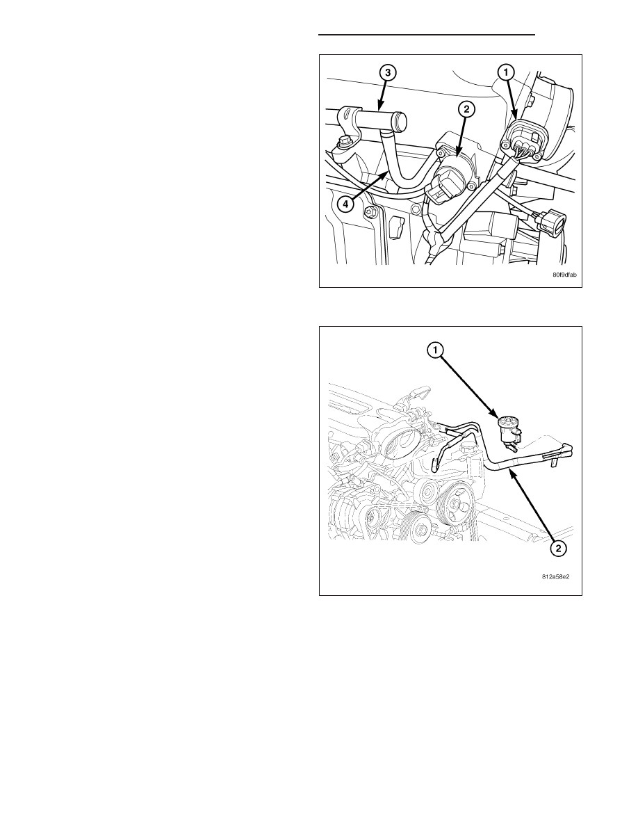
8. Disconnect the following electrical connectors:

Left cylinder head fuel injectors

MAP sensor

Engine Coolant Temperature (ECT) Sensor

Idle Speed Control Sensor (ISC)

Throttle Position Sensor (TPS) (1)

Right cylinder head fuel injectors

9. Carefully separate the fuel injector harness push

pins from the intake manifold.

10. Disconnect the purge solenoid hose from beneath

the throttle body.

11. Disconnect CCV hoses from left and right cylinder

head covers.

CAUTION: Care must be taken when removing the
No. nine cylinder inside intake manifold bolt. Fail-
ure to do so may result in personal injury or pos-
sible damage.

9 - 2458

ENGINE - 8.3L - SERVICE INFORMATION

DR/DH

12. Remove the intake manifold bolts and intake man-

ifold (2).

13. Cover the intake manifold openings with a suit-

able cover when servicing to prevent any debris
from entering cylinder heads.

INSPECTION

1. Inspect manifold for cracks or other damage.

2. Inspect manifold sealing surfaces for damage.

INSTALLATION

CAUTION: When cleaning the intake manifold and
cylinder head mating surfaces, do not use a metal
scraper because the surfaces could be cut or
ground. Instead, use a wooden or plastic scraper.

NOTE: Care must be taken to protect the intake
manifold powder coat from possible scrapes and
abrasions.

1. Clean gasket surfaces and remove covering from

intake manifold openings.

2. Carefully install the intake manifold gaskets (2) and

alignment pins (1).

DR/DH

ENGINE - 8.3L - SERVICE INFORMATION

9 - 2459

3. Set the intake manifold in position on the engine.

Install intake manifold bolts and tighten initially to 1
N·m (10 in. lbs.). Tighten bolts starting at the center
and working outward to 11 N·m (95 in. lbs.).

4. Connect CCV hoses to left and right cylinder head

covers.

5. Connect fuel line to fuel rail. Pull backward on the

quick connect fitting to ensure complete insertion.

6. Connect the brake booster vacuum hose.

7. Connect speed control cable to throttle linkage.

8. Connect the throttle cable housing to the bracket

and then attach the cable to the throttle linkage

9 - 2460

ENGINE - 8.3L - SERVICE INFORMATION

DR/DH

9. Attach the purge solenoid hose to the underside of

the throttle body housing.

10. Reconnect the following electrical connectors:

Left cylinder head fuel injectors

Engine Coolant Temperature (ECT) Sensor

MAP sensor

Idle Speed Control

Throttle Position Sensor

Right cylinder head fuel injectors

11. Install air cleaner cover assembly, connect throttle

body air inlet hose, CCV hose and connect the
Intake Air Temperature Sensor (Refer to 9 -
ENGINE/AIR INTAKE SYSTEM - INSTALLATION).

12. Connect negative battery cable.

13. With the Scan Tool, use the ASD Fuel System

Test to pressurize fuel system to check for leaks.

CAUTION: When using the ASD Fuel System Test,
the Auto Shutdown (ASD) relay will remain ener-
gized for 7 minutes or until the ignition switch is
turned to the OFF position, or Stop All Test is selected.

DR/DH

ENGINE - 8.3L - SERVICE INFORMATION

9 - 2461


Content   ..  1382  1383  1384  1385   ..