Dodge Ram Truck 1500-2500-3500. Manual - part 1335


  Index      Dodge     Dodge Ram Truck 1500-2500-3500 - service repair manual 2005 year


Search            


Content   ..  1333  1334  1335  1336   ..


Dodge Ram Truck 1500-2500-3500. Manual - part 1335
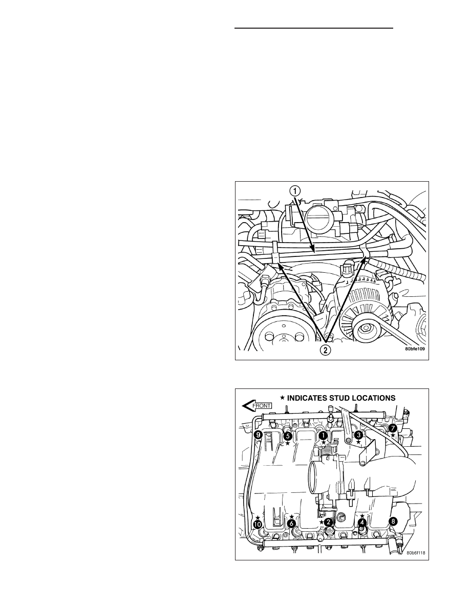


5. Disconnect brake booster hose and positive crankcase ventilation (PCV) hose.

6. Disconnect generator electrical connections.

7. Disconnect air conditioning compressor electrical connections.

8. Disconnect left and right radio suppressor straps.

9. Disconnect and remove ignition coil towers (Refer to 8 - ELECTRICAL/IGNITION CONTROL/IGNITION COIL -

REMOVAL).

10. Remove top oil dipstick tube retaining bolt and ground strap.

11. Bleed fuel system (Refer to 14 - FUEL SYSTEM/FUEL DELIVERY - STANDARD PROCEDURE).

12. Remove fuel rail (Refer to 14 - FUEL SYSTEM/FUEL DELIVERY/FUEL RAIL - REMOVAL).

13. Remove throttle body assembly and mounting bracket.

14. Drain cooling system below coolant temperature level (Refer to 7 - COOLING - STANDARD PROCEDURE).

15. Remove the heater hoses (1) from the engine

front cover and the heater core.

16. Unclip (2) and remove heater hoses and tubes

from intake manifold.

17. Remove coolant temperature sensor (Refer to 7 -

COOLING/ENGINE/ENGINE

COOLANT

TEM-

PERATURE SENSO - REMOVAL).

18. Remove intake manifold retaining fasteners in

reverse order of tightening sequence.

19. Remove intake manifold.

9 - 2262

ENGINE - 4.7L - SERVICE INFORMATION

DR/DH

CLEANING

NOTE: There is NO approved repair procedure for the intake manifold. If severe damage is found during
inspection, the intake manifold must be replaced.

Before installing the intake manifold thoroughly clean the mating surfaces. Use a suitable cleaning solvent, then air
dry.

INSPECTION

1. Inspect the intake sealing surface for cracks, nicks and distortion.

2. Inspect the intake manifold vacuum hose fittings for looseness or blockage.

3. Inspect the manifold to throttle body mating surface for cracks, nicks and distortion.

INSTALLATION

1. Install intake manifold gaskets.

2. Position intake manifold.

3. Install intake manifold retaining bolts and tighten in

sequence shown in to 12 N·m (105 in. lbs.).

4. Install left and right radio suppressor straps.

5. Install throttle body assembly.

6. Install throttle cable bracket.

7. Connect throttle cable and speed control cable to

throttle body.

8. Install fuel rail (Refer to 14 - FUEL SYSTEM/FUEL

DELIVERY/FUEL RAIL - INSTALLATION).

9. Install ignition coil towers (Refer to 8 - ELECTRI-

CAL/IGNITION

CONTROL/IGNITION

COIL

-

INSTALLATION).

10. Position and install heater hoses and tubes onto intake manifold.

11. Install the heater hoses to the heater core and engine front cover.

12. Connect electrical connectors for the following components:

Manifold Absolute Pressure (MAP) Sensor

Intake Air Temperature (IAT) Sensor

Throttle Position (TPS) Sensor

Coolant Temperature (CTS) Sensor

Idle Air Control (IAC) Motor

Ignition coil towers

Fuel injectors

13. Install top oil dipstick tube retaining bolt and ground strap.

14. Connect generator electrical connections.

15. Connect Brake booster hose and Positive crankcase ventilation (PCV) hose.

16. Fill cooling system (Refer to 7 - COOLING - STANDARD PROCEDURE).

17. Install resonator assembly and air inlet hose.

18. Connect negative cable to battery.

DR/DH

ENGINE - 4.7L - SERVICE INFORMATION

9 - 2263

MANIFOLD - EXHAUST

DESCRIPTION

The exhaust manifolds are log style with a patented flow enhancing design to maximize performance. The exhaust
manifolds are made of high silicon molybdenum cast iron. A perforated core graphite exhaust manifold gasket is
used to improve sealing to the cylinder head. The exhaust manifolds are covered by a three layer laminated heat
shield for thermal protection and noise reduction. The heat shields are fastened with a torque prevailing nut that is
backed off slightly to allow for the thermal expansion of the exhaust manifold.

REMOVAL

RIGHT EXHAUST MANIFOLD

1. Disconnect negative cable for battery.

2. Remove air cleaner assembly, resonator assembly and air inlet hose.

3. Remove accessory drive belt (Refer to 7 - COOLING/ACCESSORY DRIVE/DRIVE BELTS - REMOVAL).

4. Remove A/C compressor (Refer to 24 - HEATING & AIR CONDITIONING/PLUMBING/A/C COMPRESSOR -

REMOVAL).

5. Remove A/C accumulator support bracket fastener.

6. Drain coolant below heater hose level (Refer to 7 - COOLING - STANDARD PROCEDURE).

7. Remove heater hoses at engine.

8. Remove fasteners(4,5) attaching exhaust manifold heat shield.

9 - 2264

ENGINE - 4.7L - SERVICE INFORMATION

DR/DH

9. Remove heat shield.

10. Remove upper exhaust manifold attaching fasteners (1,3).

11. Raise vehicle on hoist.

12. Disconnect exhaust pipe from manifold.

13. Remove fasteners attaching starter. Move starter aside.

14. Remove lower exhaust manifold attaching fasteners.

15. Remove exhaust manifold and gasket. Manifold is removed from below the engine compartment.

LEFT EXHAUST MANIFOLD

1. Disconnect negative cable for battery.

2. Hoist vehicle.

3. Disconnect exhaust pipe at manifold.

4. Lower vehicle.

5. Remove the front two exhaust heat shield retaining fasteners (4,5). Raise vehicle and remove the fasteners at

rear of heat shield.

6. Remove heat shield.

7. Lower vehicle and remove the upper exhaust manifold retaining bolts (2).

8. Raise vehicle and remove the lower exhaust manifold retaining bolts (3).

9. Remove exhaust manifold and gasket. Manifold is removed from below the engine compartment.

DR/DH

ENGINE - 4.7L - SERVICE INFORMATION

9 - 2265


Content   ..  1333  1334  1335  1336   ..