Content .. 1155 1156 1157 1158 ..
Dodge Ram Truck 1500-2500-3500. Manual - part 1157
P0121-TP SENSOR VOLTAGE DOES NOT AGREE WITH MAP (CONTINUED)
2.
MAP SENSOR OPERATION
Start the engine.
With the scan tool, monitor the MAP Sensor voltage.
Snap the throttle.
Does the scan tool display MAP voltage from below 2.0 volts at idle to above 3.5 volts at WOT?
Yes
>> Go To 3
No
>> Go To 10
3.
TP SENSOR OPERATION
Ignition on, engine not running.
With the scan tool, monitor the TP Sensor voltage while slowly depressing the throttle pedal from the idle position
to the wide open throttle position.
Does voltage start at approximately 0.8 of a volt and go above 3.5 volts with a smooth transition?
Yes
>> Refer to the INTERMITTENT CONDITION Diagnostic Procedure. (Refer to 9 - ENGINE - DIAGNOSIS
AND TESTING)
Perform the POWERTRAIN VERIFICATION TEST. (Refer to 9 - ENGINE - STANDARD PROCEDURE)
No
>> Go To 4
4.
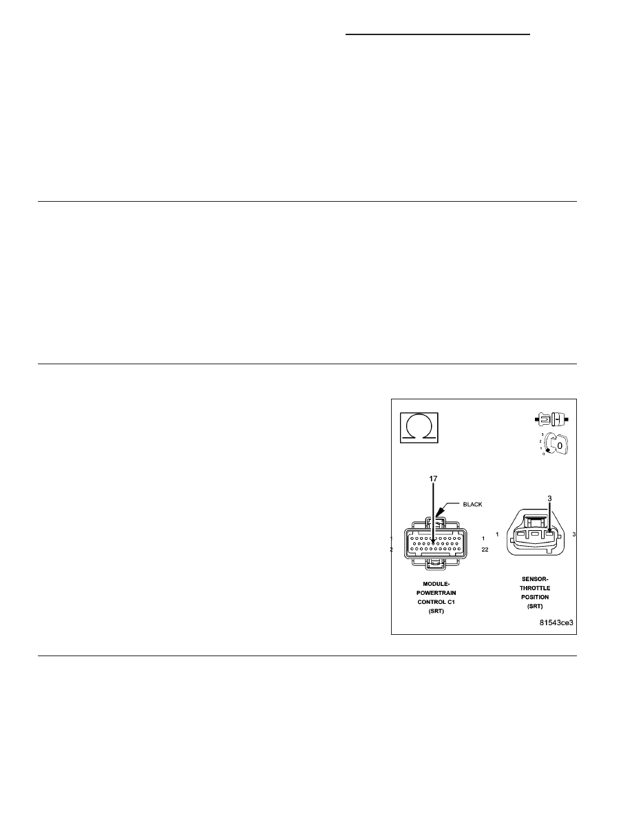
RESISTANCE IN THE (F855) 5-VOLT SUPPLY CIRCUIT
Turn the ignition off.
Disconnect the TP Sensor harness connector.
Disconnect the PCM harness connectors.
Measure the resistance of the (F855) 5-volt Supply circuit from the TP
Sensor harness connector to the PCM harness connector.
Is the resistance below 5.0 ohms?
Yes
>> Go To 5
No
>> Repair the excessive resistance in the (F855) 5-volt Sup-
ply circuit.
Perform the POWERTRAIN VERIFICATION TEST. (Refer
to 9 - ENGINE - STANDARD PROCEDURE)
9 - 1550
ENGINE - ELECTRICAL DIAGNOSTICS - SRT-10
DR/DH