Dodge Ram Truck 1500-2500-3500. Manual - part 62
 

  Index      Dodge     Dodge Ram Truck 1500-2500-3500 - service repair manual 2005 year


Search            


Content   ..  60  61  62  63   ..


Dodge Ram Truck 1500-2500-3500. Manual - part 62


C2311-STABILIZER/DIFFERENTIAL INDICATOR SUPPLY CIRCUIT HIGH

3 - 80

DIFFERENTIAL & DRIVELINE - ELECTRICAL DIAGNOSTICS

DR/DH

C2311-STABILIZER/DIFFERENTIAL INDICATOR SUPPLY CIRCUIT HIGH (CONTINUED)

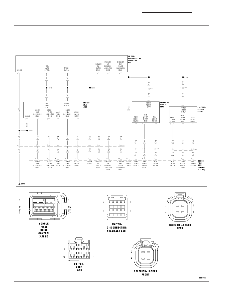
For a complete wiring diagram Refer to Section 8W.

When Monitored:
Ignition on.

Set Condition:
The FDCM sense an the voltage on the Switch Supply circuit is high.

Possible Causes

DISCONNECTING STABILIZER SWITCH

ALXE LOCKER SWITCH

(T536) SWITCH SUPPLY CIRCUIT SHORTED TO VOLTAGE

T536) SWITCH SUPPLY CIRCUIT OPEN

(T532,T533 or T534) LOCKER ILLUMINATION SENSE CIRCUIT SHORTED TO VOLTAGE

(T532,T533 or T534) LOCKER ILLUMINATION SENSE CIRCUIT OPEN

FDCM

1.

DTC ACTIVE

CAUTION: Before removing the FDCM harness connector, clean the connector and locking cam area of dirt
and debris. Failure to do so can result in the connector being jammed or damage to the locking cams on
the harness connector or module. Do not force the assist arm when releasing or installing the harness con-
nector.

NOTE: If set along with this DTC, diagnose any Stabilizer Select Switch DTC(s) first before continuing.
Turn the ignition on, engine not running

With the DRBIII

T

, read FDCM DTC(s).

Is the DTC active at this time?

Yes

>> Go To 2

No

>> Go To 9

2.

AXLE LOCKER SWITCH

NOTE: Before continuing with the below diagnostic test, ensure the FDCM harness connector seal is
installed correctly. Inspect the terminals on both harness connector and the module for damage. Failure to
do so can result in misdiagnoses of the system.
Turn the ignition off.

Disconnect the Axle Locker Switch harness connector.

Turn the ignition on.

Using a test light connected to battery voltage, probe the (T532) Locker Open Illumination Sense circuit in the Axle
Locker Switch harness connector.

With the DRBIII

T

, select System Test and actuate the Locker Open Illumination LED. Select the blinking option.

NOTE: Repeat the above test for the (T533) Locker Rear Illumination Sense circuit and (T534) Locker FR/RR
Illumination Sense circuit one at a time.

Does the test light illuminate and flash on and off at each circuit?

Yes

>> Replace the Axle Locker Switch.

Perform FDCM VERIFICATION TEST.

No

>> Go to 3

DR/DH

DIFFERENTIAL & DRIVELINE - ELECTRICAL DIAGNOSTICS

3 - 81

C2311-STABILIZER/DIFFERENTIAL INDICATOR SUPPLY CIRCUIT HIGH (CONTINUED)

3.

(T536) SWITCH SUPPLY CIRCUIT SHORTED TO VOLTAGE

Turn the ignition off.

Disconnect the Axle Locker Switch harness connector.

Disconnect the Disconnecting Stabilizer Bar Switch harness connector

Disconnect the FDCM harness connector.

Turn the ignition on.

Measure the voltage on the (T536) Switch Supply circuit in the Axle
Locker Switch harness connector.

Does the voltmeter indicate voltage present?

Yes

>> Repair the short to voltage in the Switch Supply circuit.

No

>> Go To 4

4.

(t536) SWITCH SUPPLY CIRCUIT OPEN FROM THE AXLE LOCKER SWITCH AND THE FDCM

Turn the ignition off.

Measure the resistance of the (T536) Switch Supply circuit between
the Axle Locker Switch harness connector and the FDCM harness
connector.

Is the resistance below 5.0 ohms?

Yes

>> Go to 5

No

>> Repair the open in the Switch Supply circuit.

Perform FDCM VERIFICATION TEST.

3 - 82

DIFFERENTIAL & DRIVELINE - ELECTRICAL DIAGNOSTICS

DR/DH

C2311-STABILIZER/DIFFERENTIAL INDICATOR SUPPLY CIRCUIT HIGH (CONTINUED)

5.

(T536) SWITCH SUPPLY CIRCUIT OPEN FROM THE AXLE LOCKER SWITCH AND THE DISCONNECTING
STABILIZER BAR SWITCH

Turn the ignition off.

Measure the resistance of the (T536) Switch Supply circuit between
the Axle Locker Switch harness connector and the Disconnecting Sta-
bilizer Bar Switch harness connector.

Is the resistance below 5.0 ohms?

Yes

>> Go to 6

No

>> Repair the open in the Switch Supply circuit.

Perform FDCM VERIFICATION TEST.

6.

DISCONNECTING STABILIZER BAR SWITCH

Turn the ignition off.

Connect the Axle Locker Switch harness connector.

Connect the Disconnecting Stabilizer Bar Switch harness connector

Turn the ignition on.

Measure the voltage on the (T536) Switch Supply circuit in the FDCM harness connector.

Does the voltmeter indicate voltage present?

Yes

>> Replace the Disconnecting Stabilizer Bar Switch.

No

>> Go To 7

DR/DH

DIFFERENTIAL & DRIVELINE - ELECTRICAL DIAGNOSTICS

3 - 83


Content   ..  60  61  62  63   ..