Dodge Ram Truck 1500-2500-3500. Manual - part 60
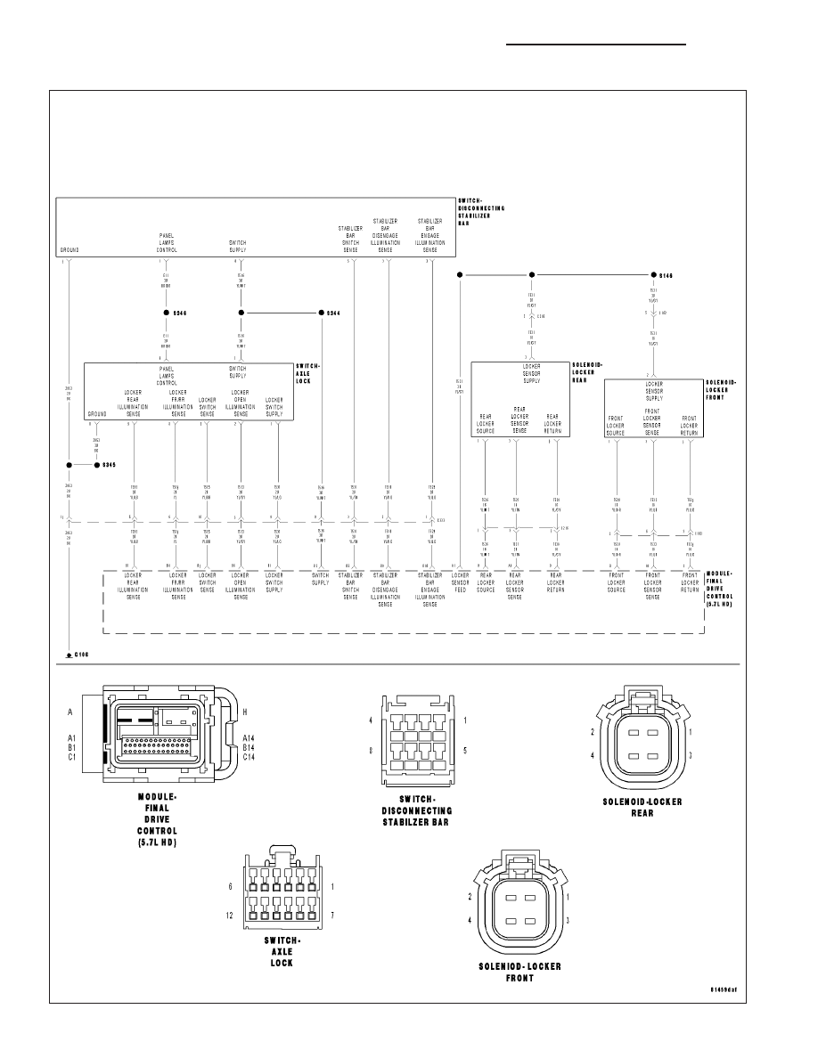
C230F-LOCKER/DIFFERENTIAL INDICATOR SUPPLY CIRCUIT PREFORMANCE
3 - 72
DIFFERENTIAL & DRIVELINE - ELECTRICAL DIAGNOSTICS
DR/DH
|
|
|
C230F-LOCKER/DIFFERENTIAL INDICATOR SUPPLY CIRCUIT PREFORMANCE 3 - 72 DIFFERENTIAL & DRIVELINE - ELECTRICAL DIAGNOSTICS DR/DH |