Dodge Ram Truck 1500-2500-3500. Manual - part 63
C2311-STABILIZER/DIFFERENTIAL INDICATOR SUPPLY CIRCUIT HIGH (CONTINUED)
7.
(T532, T533 or T534) LOCKER ILLUMINATION SENSE CIRCUIT SHORTED TO VOLTAGE
Disconnect the Axle Locker Switch harness connector.
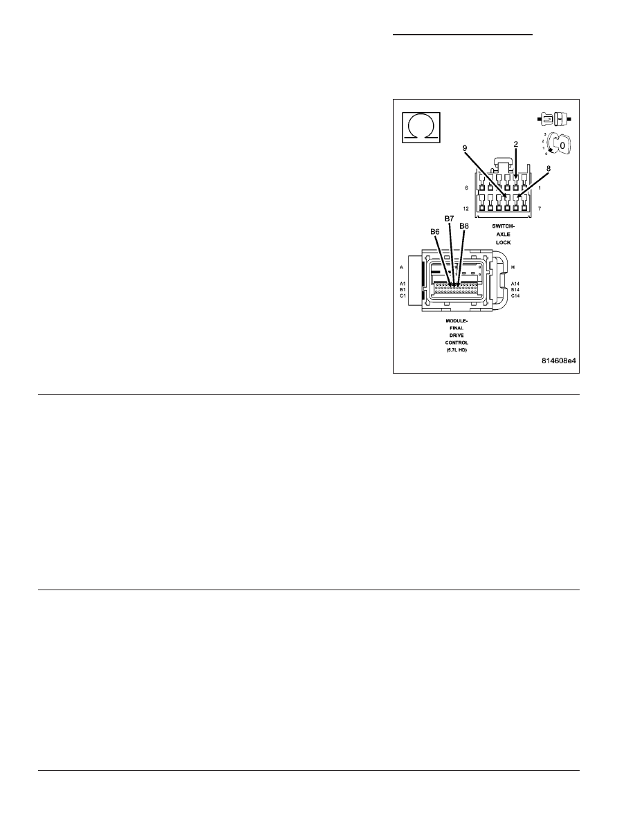
Measure the voltage at each of the following circuit at the FDCM har-
ness connector.
•
(T532) Locker Open Illumination Sense circuit
•
(T533) Locker Rear Illumination Sense circuit
•
(T534) Locker FR/RR Illumination Sense circuit
Does the voltmeter indicate voltage present for any of the
above circuit?
Yes
>> Repair the Locker Illumination Sense circuit that indicated
a short to voltage.
No
>> Go To 8
Perform FDCM VERIFICATION TEST.
8.
(T532, T533 or T534) LOCKER ILLUMINATION SENSE CIRCUIT OPEN
Measure the resistance of each of the following circuits between the FDCM harness connector and the Axle Locker
Switch harness connector.
•
(T532) Locker Open Illumination Sense circuit
•
(T533) Locker Rear Illumination Sense circuit
•
(T534) Locker FR/RR Illumination Sense circuit
Does the ohmmeter indicate each measurement below 5.0 ohms?
Yes
>> Replace the FDCM in accordance with the Service Information.
Perform FDCM VERIFICATION TEST.
No
>> Repair the Locker Illumination Sense circuit that indicated an open circuit.
Perform FDCM VERIFICATION TEST.
9.
INTERMITTENT WIRING AND CONNECTORS
The conditions necessary to set this DTC are not present at this time.
Using the schematics as a guide, inspect the wiring and connectors specific to this circuit.
Wiggle test the wiring harness and connectors while checking for shorted and open circuits.
Using the DRBIII
T
, monitor the data related to this circuit while performing the wiggle test. Look for the data to
change or for the DTC to reset.
Were there any problems found?
Yes
>> Repair as necessary.
Perform FDCM VERIFICATION TEST.
No
>> Test Complete.
3 - 84
DIFFERENTIAL & DRIVELINE - ELECTRICAL DIAGNOSTICS
DR/DH