Dodge Durango (HB). Manual - part 566


  Index      Dodge     Dodge Durango (HB) - service repair manual 2005 year


Search            


Content   ..  564  565  566  567   ..


Dodge Durango (HB). Manual - part 566


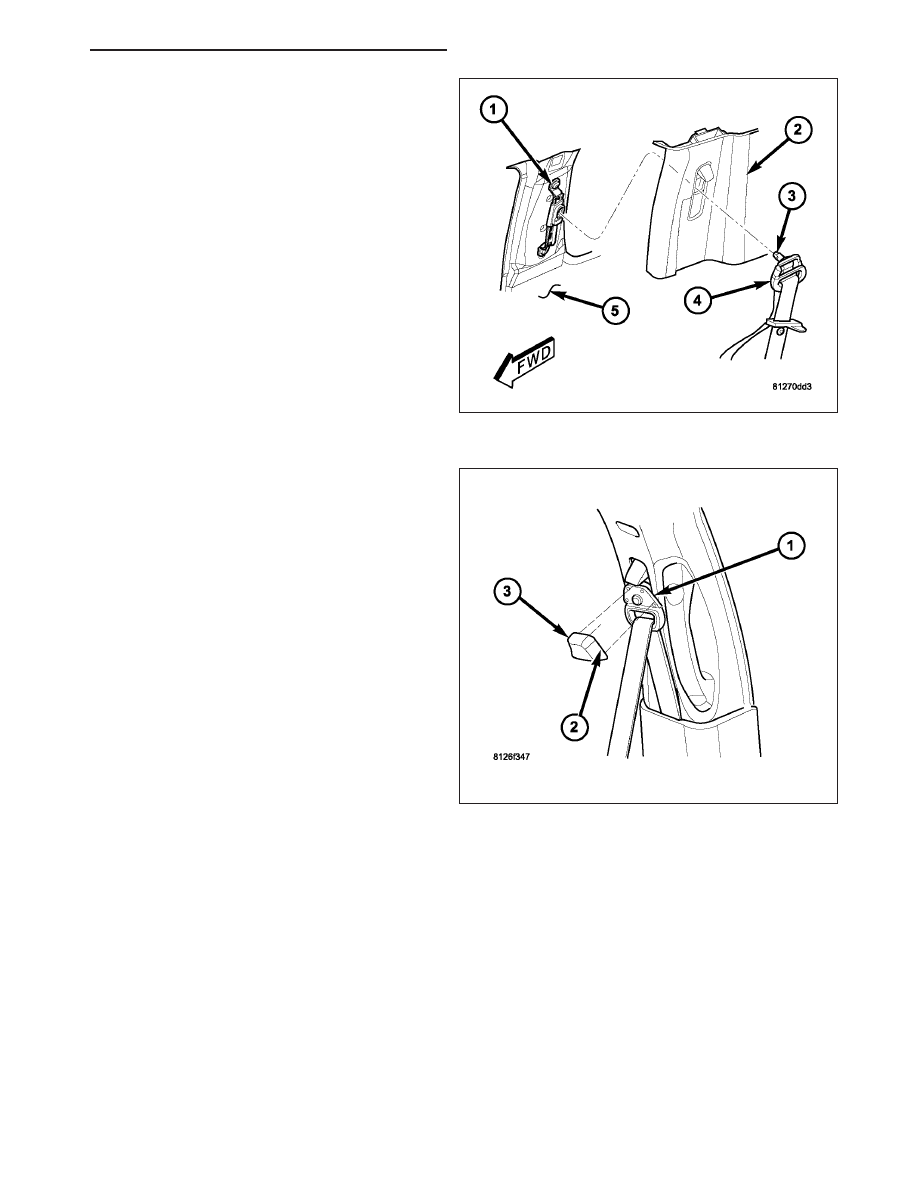
3. Reinstall the upper trim (2) onto the inside of the

C-pillar (5). (Refer to 23 - BODY/INTERIOR/C-PIL-
LAR TRIM - INSTALLATION).

4. Position the seat belt turning loop (4) to the height

adjuster (1) on the upper C-pillar.

5. Install and tighten the screw (3) that secures the

turning loop to the height adjuster. Tighten the
screw to 39 N·m (29 ft. lbs.).

6. Engage the tab (2) on the lower edge of the trim

cover (3) in the slot below the screw in the turning
loop (1). Then press the upper edge of the trim
cover over the top of the turning loop until it snaps
into place.

HB

RESTRAINTS - SERVICE INFORMATION

8O - 533

SENSOR-SEAT TRACK POSITION

DESCRIPTION

The seat track position sensor (1) is a Hall Effect-type
sensor. This sensor consists of a Hall Effect Integrated
Circuit (IC) chip encased in potting material within a
cavity of the molded plastic sensor housing. The sen-
sor housing has two integral snap features (3) and
snaps into a stamped metal bracket located on the
inboard side of one of the seat adjuster tracks on
each front seat. A molded connector receptacle (2)
integral to the sensor housing is connected to the
vehicle electrical system through a connector and take
out of the driver or passenger seat wire harness
beneath the front seat cushion frame.

The seat track position sensor cannot be adjusted or
repaired and, if faulty or damaged, the entire sensor
must be replaced.

OPERATION

The seat track position sensor is designed to provide a seat position data input to the Occupant Classification Mod-
ule (OCM) indicating whether the driver side or passenger side front seat is in a full forward or a not full forward
position. The OCM sends electronic seat position messages to the Occupant Restraint Controller (ORC) over the
Controller Area Network (CAN) data bus. The ORC uses this data as an additional logic input for use in determining
the appropriate deployment force to be used when deploying the multistage front airbags.

The seat track position sensor receives a nominal five volt supply from the OCM. The sensor communicates the
seat position by modulating the voltage returned to the OCM on a sensor data circuit. The OCM also monitors the
condition of the sensor circuits and will store a Diagnostic Trouble Code (DTC) for any fault that is detected, then
send messages to the ORC to illuminate the airbag indicator in the instrument cluster. For proper diagnosis of the
seat track position sensor, a diagnostic scan tool is required. Refer to the appropriate diagnostic information.

REMOVAL

WARNING: To avoid personal injury or death, on vehicles equipped with airbags, disable the supplemental
restraint system before attempting any steering wheel, steering column, airbag, occupant classification sys-
tem, seat belt tensioner, impact sensor, or instrument panel component diagnosis or service. Disconnect
and isolate the battery negative (ground) cable, then wait two minutes for the system capacitor to discharge
before performing further diagnosis or service. This is the only sure way to disable the supplemental
restraint system. Failure to take the proper precautions could result in accidental airbag deployment.

8O - 534

RESTRAINTS - SERVICE INFORMATION

HB

1. Disconnect and isolate the battery negative cable.

Wait two minutes for the system capacitor to dis-
charge before further service.

2. Reach under the front seat cushion to access the

seat track position sensor (3) in a bracket (1)
located on the inboard side of either the inner or
outer, driver or passenger seat track (5).

3. Disconnect the seat wire harness connector (4)

from the sensor connector receptacle located on
the rearward facing end of the sensor.

4. Using a small screwdriver, depress the snap fea-

ture (2) and pull the sensor out of the rearward fac-
ing end of the bracket.

5. Remove the sensor from under the front seat.

INSTALLATION

WARNING: To avoid personal injury or death, on vehicles equipped with airbags, disable the supplemental
restraint system before attempting any steering wheel, steering column, airbag, occupant classification sys-
tem, seat belt tensioner, impact sensor, or instrument panel component diagnosis or service. Disconnect
and isolate the battery negative (ground) cable, then wait two minutes for the system capacitor to discharge
before performing further diagnosis or service. This is the only sure way to disable the supplemental
restraint system. Failure to take the proper precautions could result in accidental airbag deployment.

1. Reach under the front edge of the front seat cush-

ion to position the seat track position sensor (3) to
the open end of the bracket (1) located on the
inboard side of either the inner or outer, driver or
passenger seat track (5).

2. Push the sensor firmly into the bracket until the

snap feature (2) locks into place.

3. Reconnect the seat wire harness connector (4) to

the sensor connector receptacle located on the
rearward facing end of the sensor. Be certain that
the latch on the connector is fully engaged.

4. Do not reconnect the battery negative cable at this

time. The supplemental restraint system verification
test procedure should be performed following ser-
vice of any supplemental restraint system compo-
nent. (Refer to 8 - ELECTRICAL/RESTRAINTS -
STANDARD

PROCEDURE

-

VERIFICATION

TEST).

5. Following successful completion of the supplemental restraint system verification test procedure, perform the

Occupant Classification System Verification Test using a diagnostic scan tool. Refer to the appropriate diagnostic
procedures.

HB

RESTRAINTS - SERVICE INFORMATION

8O - 535

SENSOR-SEAT WEIGHT

DESCRIPTION

The seat weight sensors are strain gauge-type units.
The electronic elements of the sensor are encased in
a potting material within the molded plastic sensor
housing (1). Four sensors are used in the Occupant
Classification System (OCS). A sensor is located at
each corner of the passenger side front seat.

The strain gauge for each sensor is secured through
three mounting bosses (2) by three screws and nuts
between the seat cushion frame and the seat adjuster
tracks. A molded connector receptacle (3) integral to
each sensor housing is connected to the vehicle elec-
trical system through a dedicated connector and take
out of the passenger seat wire harness beneath the
seat cushion frame.

The seat weight sensors cannot be adjusted or
repaired and, if faulty or damaged, the entire sensor
must be replaced.

OPERATION

The seat weight sensor units are designed to sense the relative weight of a load applied to the passenger side front
seat, which provides a logic input to the microprocessor of the Occupant Classification Module (OCM). When a load
is applied to the seat, the strain gauge of each sensor is flexed causing a change of electrical resistance through
the strain gauge. These changes in resistance are measured by the sensor and the internal sensor circuitry
changes the sensor output voltage.

Each weight sensor receives a nominal five volts and a ground through parallel hard wired circuits from the OCM.
The OCM then monitors the output voltage of each sensor on dedicated hard wired data communication circuits.
The hard wired circuits between the sensors and the OCM may be diagnosed and tested using conventional diag-
nostic tools and procedures. However, the most reliable, efficient, and accurate means to diagnose the seat weight
sensor inputs to the OCM, and the electronic message communication between the OCM and the Occupant
Restraint Controller (ORC) requires the use of a diagnostic scan tool. Refer to the appropriate diagnostic
information.

REMOVAL

WARNING: To avoid personal injury or death, on vehicles equipped with airbags, disable the supplemental
restraint system before attempting any steering wheel, steering column, airbag, occupant classification sys-
tem, seat belt tensioner, impact sensor, or instrument panel component diagnosis or service. Disconnect
and isolate the battery negative (ground) cable, then wait two minutes for the system capacitor to discharge
before performing further diagnosis or service. This is the only sure way to disable the supplemental
restraint system. Failure to take the proper precautions could result in accidental airbag deployment.

WARNING: To avoid personal injury or death on vehicles equipped with the Occupant Classification System
(OCS), do not modify the front passenger seat assembly or center floor console in any way. Do not use any
prior year, subsequent year, secondary or aftermarket seat trim covers. At no time should any Supplemental
Restraint System (SRS) or OCS component be modified or replaced with any part except those which are
specified for the particular vehicle application in the DaimlerChrysler Mopar Parts Catalog. Failure to
observe these precautions could cause an OCS miscalibration condition, which may result in the passenger
airbag failing to deploy when required or deploying when not required.

8O - 536

RESTRAINTS - SERVICE INFORMATION

HB


Content   ..  564  565  566  567   ..