Dodge Durango (DN). Manual - part 435
 

  Index      Dodge     Dodge Durango (DN) - service repair manual 2000 year


Search            


Content   ..  433  434  435  436   ..


Dodge Durango (DN). Manual - part 435


(2) Remove accessory drive belt refer to Group 7,

Cooling System for procedure.

(3) Remove A/C compressor mouning fasteners and

set aside.

(4) Drain cooling system. Refer to Group 7, Cooling

System for procedure.

(5) Remove upper radiator hose.
(6) Using Special Tools 6958 Spanner with Adapter

Pins 8346 loosen fan and viscous assembly from
water pump (Fig. 126).

(7) Remove fan and viscous assembly.

(8) Disconnect electrical connector for fan mounted

inside radiator shroud.

(9) Remove radiator shroud attaching fasteners.

NOTE: Transmission cooler line snaps into shroud
lower right hand corner.

(10) Remove radiator shroud.
(11) Remove crankshaft damper bolt.
(12) Remove damper using Special Tools 8513

Insert and 1026 Three Jaw Puller (Fig. 127).

(13) Using Special Tool 8511, remove crankshaft

front seal (Fig. 128).

INSTALLATION

CAUTION: To prevent severe damage to the Crank-
shaft, Damper or Special Tool 8512, thoroughly
clean the damper bore and the crankshaft nose
before installing Damper.

(1) Using Special Tool 8348 and 8512, install

crankshaft front seal (Fig. 129).

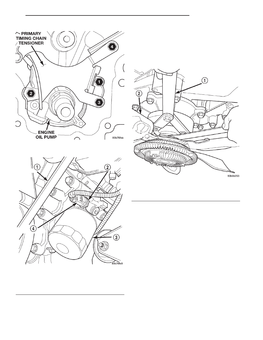
Fig. 124 Oil Pump and Primary Timing Chain

Tightening Sequence

Fig. 125 Oil Pressure Sending Unit

1 – BELT
2 – OIL PRESSURE SENSOR
3 – OIL FILTER
4 – ELEC. CONNECTOR

Fig. 126 Fan Assembly—Removal/Installation

1 – SPECIAL TOOL 6958 SPANNER WRENCH WITH ADAPTER

PINS 8346

2 – FAN

DN

4.7L ENGINE

9 - 71

REMOVAL AND INSTALLATION (Continued)

CAUTION: Special Tool 8512, is assembled in a
specific sequence. Failure to assemble this tool in
this sequence can result in tool failure and severe
damage to either the tool or the crankshaft.

(2) Assemble Special Tool 8512 as follows, The nut

is threaded onto the shaft first. Then the roller bear-
ing is placed onto the threaded rod (The hardened
bearing surface of the bearing MUST face the nut).
Then the hardened washer slides onto the threaded
rod (Fig. 130). Once assembled coat the threaded
rod’s threads with Mopar

t Nickel Anti-Seize or (Loc-

tite No. 771).

(3) Align crankshaft damper slot with key in

crankshaft. Slide damper onto crankshaft slightly.

(4) Using Special Tool 8512 press damper onto

crankshaft (Fig. 131).

(5) Install then tighten crankshaft damper bolt to

175 N·m (130 ft. lbs.).

(6) Install radiator shroud and tighten fasteners to

11 N·m (95 in. lbs.).

(7) Connect electrical connector for shroud fan.
(8) Install fan and viscous assembly.
(9) Using Special Tools 6958 Spanner with Adapter

Pins 8346 tighten fan and viscous assembly to water
pump (Fig. 126).

(10) Install upper radiator hose.
(11) Install A/C compressor and tighten fasteners

to 54 N·m (40 ft. lbs.).

(12) Install accessory drive belt refer to Group 7,

Cooling System for procedure.

(13) Refill cooling system. Refer to Group 7, Cool-

ing System for procedure.

(14) Connect negative cable to battery.

Fig. 127 Crankshaft Damper—Removal

1 – SPECIAL TOOL 8513 INSERT
2 – SPECIAL TOOL 1026

Fig. 128 Crankshaft Front Seal—Removal

1 – SPECIAL TOOL 8511

Fig. 129 Crankshaft Front Seal—Installation

1 – TIMING CHAIN COVER
2 – SPECIAL TOOL 8348
3 – SPECIAL TOOL 8512

9 - 72

4.7L ENGINE

DN

REMOVAL AND INSTALLATION (Continued)

CRANKSHAFT OIL SEAL—REAR

REMOVAL

NOTE: This procedure can be preformed in vehicle.

(1) If being preformed in vehicle, remove the

transmission. Refer to Group 21, Transmission and
Transfer Case.

(2) Remove the flexplate. Refer to procedure in

this section.

NOTE: The crankshaft oil seal CAN NOT be reused
after removal.

NOTE: The crankshaft rear oil seal remover Special
Tool 8506 must be installed deeply into the seal.
Continue to tighten the removal tool into the seal
until the tool can not be turned farther. Failure to
install tool correctly the first time will cause tool to
pull free of seal without removing seal from engine.

(3) Using Special Tool 8506 (Fig. 132), remove the

crankshaft rear oil seal.

INSTALLATION

(1) Position the magnetic seal guide Special Tool

8349–2 (Fig. 133) onto the crankshaft rear face. Then
position the crankshaft rear oil seal onto the guide.

(2) Using Special Tools 8349 Crankshaft Rear Oil

Seal Installer and C-4171 Driver Handle (Fig. 134),
with a hammer, tap the seal into place. Continue to
tap on the driver handle until the seal installer seats
against the cylinder block crankshaft bore.

(3) Install the flexplate.
(4) If removed, install the transmission.

Fig. 130 Proper Assembly Method for Special Tool

8512

1 – BEARING
2 – NUT
3 – THREADED ROD
4 – BEARING HARDENED SURFACE (FACING NUT)
5 – HARDENED WASHER

Fig. 131 Crankshaft Damper—Installation

1 – SPECIAL TOOL 8512

Fig. 132 Crankshaft Rear Oil Seal Removal

1 – REAR CRANKSHAFT SEAL
2 – SPECIAL TOOL 8506

DN

4.7L ENGINE

9 - 73

REMOVAL AND INSTALLATION (Continued)

ENGINE CORE PLUGS

REMOVAL

(1) Drain the cooling system. Refer to Group 7,

Cooling System for procedure.

(2) Using a blunt tool such as a drift or a screw

driver and a hammer, strike the bottom edge of the
cup plug (Fig. 135).

(3) Using a suitable pair of pliers, grasp the core

plug and remove.

INSTALLATION

NOTE: Thoroughly clean core plug bore, remove all
of the old sealer.

(1) Coat the edges of the engine core plug and the

core plug bore with Mopar Gasket Maker, or equiva-
lent.

NOTE: It is not necessary to wait for the sealant to
cure on the core plugs. The cooling system can be
filled and the vehicle returned to service immedi-
ately.

(2) Using proper plug driver, drive core plug into

the core plug bore. The sharp edge of the core plug
should be at least 0.50 mm (0.020 in.) inside the lead
in chamfer.

(3) Refill the cooling system.

DISASSEMBLY AND ASSEMBLY

OIL PUMP

DISASSEMBLE

(1) Remove oil pump cover screws and lift off cover

plate.

(2) Remove pump inner and outer rotors.

Fig. 133 Crankshaft Rear Oil Seal Guide Special

Tool 8349–2 and Oil Seal

1 – REAR CRANKSHAFT SEAL
2 – SPECIAL TOOL 8349–2 GUIDE

Fig. 134 Crankshaft Rear Oil Seal Installation

1 – REAR CRANKSHAFT SEAL
2 – SPECIAL TOOL 8349–1 INSTALLER
3 – SPECIAL TOOL C-4171 HANDLE

Fig. 135 Engine Core Plug Removal

1 – CYLINDER BLOCK
2 – REMOVE PLUG WITH PLIERS
3 – STRIKE HERE WITH HAMMER
4 – DRIFT PUNCH
5 – CUP PLUG

9 - 74

4.7L ENGINE

DN

REMOVAL AND INSTALLATION (Continued)


Content   ..  433  434  435  436   ..