Dodge Durango (DN). Manual - part 433
(12) Place blocks of wood between engine brackets
and lower mounts to provide stability to engine.
NOTE: Do not pry on oil pan or oil pan gasket.
Gasket is mounted to engine and does not come
out with oil pan.
(13) Remove the oil pan mounting bolts and oil
pan (Fig. 108).
(14) Unbolt oil pump pickup tube and remove tube
and oil pan gasket from engine.
INSTALLATION
(1) Clean the oil pan gasket mating surface of the
bedplate and oil pan.
(2) Position the oil pan gasket and pickup tube
with new o-ring. Install the mounting bolt and nuts.
Tighten bolt and nuts to 28 N·m (20 ft. lbs.).
(3) Position the oil pan and install the mounting
bolts. Tighten the mounting bolts to 15 N·m (11 ft.
lbs.) in the sequence shown (Fig. 108).
(4) Raise the engine and remove the blocks of
wood.
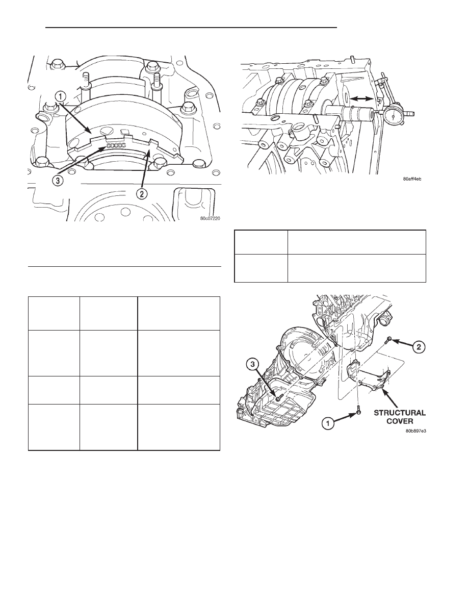
Fig. 104 Main Bearing Markings on Target Wheel
1 – REARMOST CRANKSHAFT COUNTER WEIGHT
2 – TARGET WHEEL
3 – MAIN BEARING SELECT FIT MARKINGS
MAIN BEARING SELECTION CHART—4.7L
GRADE
SIZE mm
(in.)
FOR USE WITH
MARKING
JOURNAL SIZE
A
0.008 mm
U/S
63.488–63.496 mm
(0.0004 in.)
U/S
(2.4996–2.4999 in.)
B
NOMINAL
63.496–63.504 mm
(2.4999–2.5002 in.)
C
0.008 mm
O/S
63.504–63.512 mm
(0.0004 in.)
O/S
(2.5002–2.5005 in.)
Fig. 105 Checking Crankshaft End Play—Typical
CRANKSHAFT END PLAY SPECIFICATION
CHART
New Part:
0.052 - 0.282mm
Specification
(0.002 - 0.011 in.)
Wear Limit:
0.43mm
(0.017 in.)
Fig. 106 Structural Dust Cover Removal /
Installation
DN
4.7L ENGINE
9 - 63
REMOVAL AND INSTALLATION (Continued)