Dodge Durango (DN). Manual - part 434
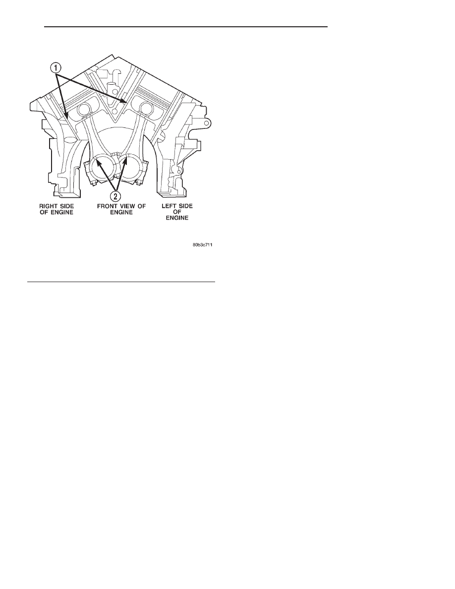
(7) Rotate crankshaft until connecting rod journal
is on the center of cylinder bore. Insert rod and pis-
ton into cylinder bore and carefully position connect-
ing rod guides over crankshaft journal.
(8) Tap piston down in cylinder bore using a ham-
mer handle. While at the same time, guide connect-
ing rod into position on rod journal.
CAUTION: Connecting Rod Bolts are Torque to
Yield Bolts and Must Not Be Reused. Always
replace the Rod Bolts whenever they are loosened
or removed.
(9) Lubricate rod bolts and bearing surfaces with
engine oil. Install connecting rod cap and bearing.
Tighten bolts to 27 N·m (20 ft. lbs.) plus 90°.
(10) Install the following components: (Refer to
procedures in this section)
• Cylinder head(s).
• Timing chain and cover.
• Cylinder head covers.
• Oil pan and gasket/windage tray.
(11) Fill crankcase with proper engine oil to cor-
rect level.
(12) Connect negative cable to battery.
CRANKSHAFT
REMOVAL
NOTE: To remove the crankshaft from the engine,
the engine must be removed from the vehicle.
(1) Remove the engine. Refer to Engine Assembly
in this section for procedure.
(2) Remove the engine oil pump. Refer to Oil
Pump in this section for procedure.
CAUTION: DO NOT pry on the oil pan gasket when
removing the oil pan, The oil pan gasket is mounted
to the cylinder block in three locations and will
remain attached to block when removing oil pan.
Gasket can not be removed with oil pan.
(3) Remove oil pan bolts and oil pan.
(4) Remove the oil pump pickup tube and oil pan
gasket /windage tray.
(5) Remove the bedplate mounting bolts. Note the
location of the three stud bolts for installation.
(6) Remove the connecting rods from the crank-
shaft.
CAUTION: The bedplate to cylinder block mating
surface is a critical sealing surface. Do not pry on
or damage this surface in anyway.
NOTE: The bedplate contains the lower main bear-
ing halves. Use care when handling bedplate as not
to drop or damage bearing halves. Installing main
bearing halves in the wrong position will cause
sever damage to the crankshaft.
NOTE: The bedplate has pry points cast into it. Use
these points only. The pry points are on both the
left and right sides, only the left side is shown.
(7) Carefully pry on the pry points (Fig. 117) to
loosen the bedplate then remove the bedplate.
CAUTION: When removing the crankshaft, use care
not to damage bearing surfaces on the crankshaft.
(8) Remove the crankshaft.
(9) Remove the crankshaft tone wheel.
INSPECTION
NOTE: Thoroughly
inspect
the
connecting
rod
bearing bores and main bearing bores for scoring,
blueing or severe scratches. Further disassembly
may be required.
Fig. 116 Piston and Connecting Rod Positioning
1 – MAJOR THRUST SIDE OF PISTON
2 – OIL SLINGER SLOT
DN
4.7L ENGINE
9 - 67
REMOVAL AND INSTALLATION (Continued)