Chrysler Le Baron, Dodge Dynasty, Plymouth Acclaim. Manual - part 356


  Index      Dodge     Chrysler Le Baron, Dodge Dynasty, Plymouth Acclaim - service repair manual 1993 year


Search            


Content   ..  354  355  356  357   ..


Chrysler Le Baron, Dodge Dynasty, Plymouth Acclaim. Manual - part 356


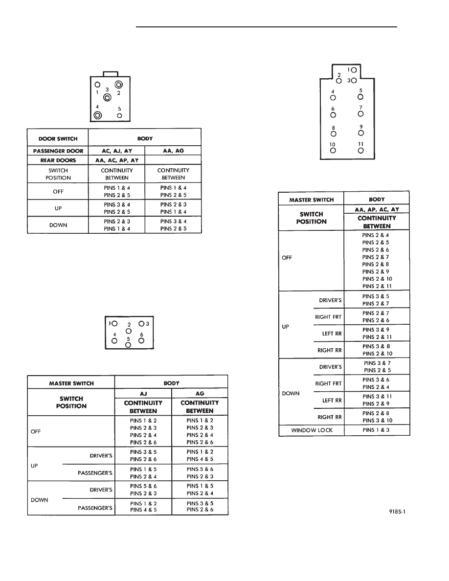
WINDOW SWITCH CONTINUITY

8S - 2

POWER WINDOWS

Ä

(4) Reverse battery leads (steps 1 and 2 above) and

window should now move. If window does not move,
remove motor. See below for motor removal from ve-
hicle.

(5) If window moved completely up or down, motor

should be reversed one more time (reverse leads from
step 4) to complete a full window travel inspection.

GEAR AND PINION REPLACEMENT AND
LUBRICATION

The window glass and mechanism have been found

to move freely. The window motor works. But the
glass does not move up or down. The motor gear and
pinion will need to be replaced (Fig. 1).

When gear and pinion assembly is replaced in gear

box, lubrication of gear box, gear pinion and seal is
necessary.

In the event there is no lubricant in gear box, fill

with MOPAR multi-mileage lubricant or equivalent.
Apply a liberal amount of lubricant to inside area of
seal marked A as illustrated in Fig. 1 and sealing
surface at center area of gear and pinion coupling.
Also lubricate center gear box shaft and worm gear.

MOTOR REPLACEMENT CONVENTIONAL
REGULATORS

The following procedure describes replacement of a

defective motor without removing window regulator
or detaching any window system components. This
method of motor replacement is not acceptable if any
of window system parts are loosened or removed from
door such as:
• Lift channels

• Up stops

• Tracks and pivot brackets

• Are already loose by deficiency

• Are to be loosened or removed from the door.

Then use method of repair where entire regulator

is removed from door (Fig. 2 through 9).

REMOVAL

(1) Raise window to full UP position and keep it

there at all times while replacing motor. If window is in
any position other than full UP and motor is separated
from spring loaded regulator, then regulator counterbal-
ance spring will tend to propel window upwards.

WARNING:PLACE A WINDOW BLOCK IN DOOR
THAT WILL POSITIVELY PREVENT WINDOW FROM
GOING DOWN. THIS ACTION WILL PREVENT IN-
JURY THAT COULD BE CAUSED BY INCORRECT
INSTALLATION

OF

COUNTERBALANCE

SPRING

OR UPWARD MOVEMENT OF THE WINDOW.

(2) Disconnect wiring connector from motor which

is located about eleven inches from motor.

(3) Remove three mounting screws that hold motor

gearbox to regulator. Remove third screw that se-
cures motor tie-down bracket to inner panel if so
equipped. There are three holes in inner panel which
provide access to three mounting screws that secure
gearbox to regulator (Fig. 2).

Fig. 1 Motor Lubrication

Fig. 2 Electric Motor Mounting—Conventional

Regulators

Fig. 3 Front Door Power Window—AA Body

Ä

POWER WINDOWS

8S - 3

For AJ body vehicles, it will be necessary to reach

through opening in inner door panel and around be-
hind regulator to gain access to motor gearbox re-
taining screws.

Fig. 6 Power Window Four Door—AP Body

Fig. 7 Power Window Convertible—AJ Body

Fig. 8 Power Window—AJ Body

Fig. 4 Rear Door Power Window—AA Body

Fig. 5 Power Window Two Door—AP Body

8S - 4

POWER WINDOWS

Ä

(4) To remove motor from regulator, grip motor

housing and pull motor towards inner or outer panel,
depending on regulator type. Some rocking or twist-
ing action may be necessary to disengage motor from
regulator.

WARNING:DO NOT HAVE ANY HANDS OR FIN-
GERS IN SECTOR GEAR AREA WHERE THEY CAN
BE PINCHED BY SMALL MOVEMENTS OF REGULA-
TOR LINKAGE.

INSTALLATION

New motor gearbox retaining screw holes are not

threaded. It may be desirable to tap holes before at-
tempting assembly.

(1) Install new motor on regulator by positioning

motor gearbox so that it engages regulator sector
teeth.

(2) Position motor so that center post gearbox fits

into its pilot hole in plate. A slight rotational or
rocking movement may be necessary to bring three
motor gearbox screw holes into proper position.

(3) Install three gearbox screws and one tie down

bracket screw, if applicable. Tighten to 5 to 7 N

Im

(50 to 60 in. lbs.) torque.

(4) Connect pigtail wiring harness connector.
(5) Remove window block.
(6) Actuate regulator with switch to verify satis-

factory operation.

BENCH REPAIR OF REGULATOR AND MOTOR
CONVENTIONAL REGULATORS

To repair or inspect the entire electric window reg-

ulator, remove from the door as follows:

REMOVAL

(1) Disconnect wiring connector from motor.
(2) Hold glass in the up position.
(3) Remove rivets and/or screws that hold regula-

tor and motor to inner door panel.

(4) Maneuver regulator assembly by hand to disen-

gage the drive arm slider from the glass lift channel.
Remove from door.

REPAIR

If entire regulator is not being replaced, repair as

follows:

WARNING:REMOVE COUNTER BALANCE SPRING
BEFORE THE MOTOR IS REMOVED. IF IT IS NOT,
THE SPRING TENSION WILL CAUSE THE REGULA-
TOR ARMS TO CLOSE AS SOON AS THE MOTOR
IS REMOVED AND COULD SERIOUSLY INJURE
YOUR FINGERS 
.

(1) Remove regulator as described above.
(2) Secure regulator in vise to prevent sector gear

from rotating.

(3) Remove counter balance spring.
(4) Remove three motor attaching screws and re-

move motor.

(5) Inspect regulator for:

(a) Sector gear teeth must not be broken or se-

verely worn.

(b) All rivets and sliders must be securely at-

tached.

(c) Parts must not be bent or cracked.
(d) Sector gear must rotate freely.
(e) Perform window lift motor test as described

above.

INSTALLATION

(1) Install motor and attach with three motor at-

taching screws. If installation of new motor is neces-
sary, it may be desirable to tap motor retaining
screw holes.

(2) Install counter balance spring.
(3) Replace regulator in door by reversing Removal

steps 1, 2 and 3.

(4) Regulators may be secured to door panel using

rivets or 1/4-20 X 1/2 screws and nuts.

MOTOR REPLACEMENT—FLEX DRIVE
REGULATORS

REMOVAL

(1) Raise or lower window to the proper access hole

position and remove screw that attaches the flex rack
to the drive arm (Fig. 10). Hold the glass in that po-
sition.

(2) Remove

the

regulator

attaching

rivets

by

knocking out the rivet center mandrel and drilling

Fig. 9 Rear Door Power Window—AC, and AY Body

Ä

POWER WINDOWS

8S - 5


Content   ..  354  355  356  357   ..