Chrysler Le Baron, Dodge Dynasty, Plymouth Acclaim. Manual - part 239


  Index      Dodge     Chrysler Le Baron, Dodge Dynasty, Plymouth Acclaim - service repair manual 1993 year


Search            


Content   ..  237  238  239  240   ..


Chrysler Le Baron, Dodge Dynasty, Plymouth Acclaim. Manual - part 239


(7) Using needle nose pliers, install the 3 brake fluid

reservoir to hydraulic assembly retaining pins (Fig.
14). Be sure retaining pins are fully installed with
barbs extending out past reservoir on opposite
side.

(8) Install high pressure hose banjo fitting onto

hydraulic assembly and install banjo fitting attaching
bolt. Torque banjo fitting to hydraulic assembly banjo
bolt to 13 N

Im (10 ft. lbs.).

(9) Install brake fluid spray shield onto hydraulic

assembly. Install bladder accumulator into hydraulic
assembly by hand (using care not to cross thread
accumulator) until O-ring seal is fully seated into
hydraulic assembly.

(10) Using Oil Filter Band Wrench, Special Tool

C-4065 or equivalent, (Fig. 12) torque bladder accumu-
lator to 48 N

Im (35 ft. lbs.).

(11) Fill hydraulic assembly fluid reservoir to the top

of the screen on the filter\trainer. Use only fresh clean
brake fluid conforming to DOT 3 requirements, such as
Mopar

t or equivalent.

(12) Bleed the brake hydraulic system using proce-

dure shown in Bleeding Brake System in this section of
the service manual.

DIFFERENTIAL PRESSURE SWITCH

REMOVE

WARNING: FAILURE TO FULLY DE-PRESSURIZE THE
HYDRAULIC BLADDER ACCUMULATOR PRIOR TO
REMOVING

DIFFERENTIAL

PRESSURE

SWITCH.

WILL RESULT IN PERSONAL INJURY AND/OR DAM-
AGE TO PAINTED SURFACES OF THE VEHICLE.

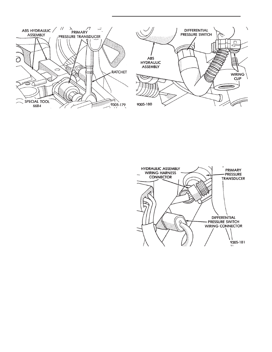
To remove the differential pressure switch (Fig. 18),

from the hydraulic assembly, removal of the hydraulic
assembly from the vehicle is not required.

(1) De-pressurize hydraulic bladder accumulator on

hydraulic assembly by pumping the brake pedal a
minimum of 40 times. Refer to the procedure as de-
scribed in De-Pressurizing Hydraulic Accumulator
listed earlier in this section.

(2) Disconnect the hydraulic assembly wiring har-

ness connector from the primary pressure transducer
(Fig. 19).

(3) Disconnect differential pressure switch wiring

harness connector from hydraulic assembly wiring
harness (Fig. 19). Do not attempt to remove wiring
harness from differential pressure switch.

(4) Raise vehicle on a frame contact type hoist. See

Hoisting in the Lubrication And Maintenance section
of this manual, for the required lifting procedure to be
used for this vehicle.

(5) Using a long extension and Socket, Special Tool

6684 loosen and remove differential pressure switch
from bottom of hydraulic assembly (Fig. 20)

Fig. 18 Differential Pressure Switch Location

Fig. 19 Primary Pressure Transducer And Differen-

tial Pressure Switch Wiring Harness Connectors

Fig. 17 Primary Pressure Transducer Removal And

Replacement

5 - 110

ANTI-LOCK 10 BRAKE SYSTEM

Ä

INSTALL

(1) Install differential pressure switch into hydrau-

lic assembly by hand, until fully threaded into hy-
draulic assembly. Then torque differential pressure
switch, into hydraulic assembly, using Socket, Spe-
cial Tool 6684, to 1.5 N

Im (13 in. lbs.).

(2) Lower vehicle
(3) Connect differential pressure switch wiring

harness connector into hydraulic assembly wiring
harness (Fig. 19).

(4) Connect the hydraulic assembly wiring harness

connector into the primary pressure transducer (Fig.
19).

(5) Turn the ignition switch to the on position and

let the system pressurize. Check for any signs of
leakage at the differential pressure switch.

(6) Fully de-pressurize the hydraulic assembly a

second time to purge any air out that may have en-
tered hydraulic assembly when the differential pres-
sure switch was removed. Turn the ignition switch to
the on position and let the system pressurize again.

(7) Fill hydraulic assembly fluid reservoir to the

top of the screen on the filter\trainer. Use only fresh
clean brake fluid conforming to DOT 3 requirements,
such as Mopar

t or equivalent.

(8) Road test vehicle to insure that the brake sys-

tem is performing correctly.

BOOST PRESSURE TRANSDUCER

REMOVE

WARNING: FAILURE TO FULLY DE-PRESSURIZE
THE HYDRAULIC BLADDER ACCUMULATOR PRIOR
TO REMOVING BOOST PRESSURE TRANSDUCER.
MAY RESULT IN PERSONAL INJURY AND/OR DAM-
AGE TO PAINTED SURFACES OF THE VEHICLE.

To remove the boost pressure transducer (Fig. 21),

from the hydraulic assembly, removal of the hydrau-
lic assembly from the vehicle is not required.

(1) De-pressurize hydraulic bladder accumulator on

hydraulic assembly by pumping the brake pedal a
minimum of 40 times. Refer to the procedure as de-
scribed in De-Pressurizing Hydraulic Accumulator
listed earlier in this section.

(2) Raise vehicle on a frame contact type hoist. See

Hoisting in the Lubrication And Maintenance section
of this manual, for the required lifting procedure to
be used for this vehicle.

(3) Disconnect hydraulic assembly wiring harness

connectors from the dual function pressure switch
and boost pressure transducer (Fig. 21).

(4) Using a long extension and Socket, Special Tool

6607, remove dual function pressure switch from bot-
tom of hydraulic assembly (Fig. 22)

(5) Remove boost pressure transducer from hydrau-

lic assembly, from under vehicle using a long exten-
sion and Socket, Special Tool 6684 (Fig. 23).

Fig. 20 Differential Pressure Switch Removal And

Replacement

Fig. 21 Boost Pressure Transducer Location

Fig. 22 Remove And Install Dual Function Pressure

Switch

Ä

ANTI-LOCK 10 BRAKE SYSTEM

5 - 111

INSTALL

(1) Install boost pressure transducer (Fig. 23) into

hydraulic assembly by hand, until O-ring is fully
seated into hydraulic assembly. Then torque boost

pressure transducer, into hydraulic assembly, using
Socket, Special Tool 6684, to 12 N

Im (106 in. lbs.).

(2) Install Dual Function Pressure Switch (Fig. 22)

into hydraulic assembly by hand, until O-ring is
fully seated into hydraulic assembly. Then torque
dual function pressure switch, into hydraulic assem-
bly, using Socket, Special Tool 6607, to 12 N

Im (106

in. lbs.).

(3) Connect hydraulic assembly wiring harness

connectors, onto the dual function pressure switch
and boost pressure transducer (Fig. 21).

(4) Turn the ignition switch to the on position and

let the system pressurize. Check for any signs of
leakage at the differential pressure switch.

(5) Fully de-pressurize the hydraulic assembly a

second time to purge any air out that may have en-
tered hydraulic assembly when the differential pres-
sure switch was removed. Turn the ignition switch to
the on position and let the system pressurize again.

(6) Fill hydraulic assembly fluid reservoir to the

top of the screen on the filter\trainer. Use only fresh
clean brake fluid conforming to DOT 3 requirements,
such as Mopar

t or equivalent.

(7) Road test vehicle to insure that the brake sys-

tem is performing correctly.

Fig. 23 Remove And Install Boost Pressure

Transducer

5 - 112

ANTI-LOCK 10 BRAKE SYSTEM

Ä

ANTI-LOCK BRAKE SYSTEM—BENDIX ANTI-LOCK 6 AA,AG,AJ,AP BODY

INDEX

page

page

ABS Brake System Diagnosis

. . . . . . . . . . . . . . 123

ABS Brake System Diagnostic Features

. . . . . . 125

ABS Computer System Service Precautions

. . . 124

ABS General Service Precautions

. . . . . . . . . . . 124

Anti-Lock Brake System Components

. . . . . . . . 116

Anti-Lock Brake System Definitions

. . . . . . . . . . 113

Anti-Lock Brakes Operation and Performance

. . 115

Anti-Lock System Relays and Warning Lamps

. . 120

Controller Anti-Lock Brake (CAB)

. . . . . . . . . . . . 119

Diagnostic Connector

. . . . . . . . . . . . . . . . . . . . . 120

Electronic Components

. . . . . . . . . . . . . . . . . . . 130

General Information

. . . . . . . . . . . . . . . . . . . . . . 113

Hydraulic Circuits and Valve Operation

. . . . . . . 121

Major Components

. . . . . . . . . . . . . . . . . . . . . . 114

Mechanical Diagnostics and Service Procedures . 125
Normal Braking System Function

. . . . . . . . . . . . 114

On-Car ABS Brake System Service

. . . . . . . . . . 126

Specifications

. . . . . . . . . . . . . . . . . . . . . . . . . . 135

System Self-Diagnostics

. . . . . . . . . . . . . . . . . . 115

Vehicle Performance

. . . . . . . . . . . . . . . . . . . . . 115

Warning Systems Operation

. . . . . . . . . . . . . . . 116

GENERAL INFORMATION

The purpose of the Anti-Lock Brake System (ABS)

is to prevent wheel lock-up under heavy braking con-
ditions on virtually any type of road surface. Anti-
Lock Braking is desirable because a vehicle which is
stopped without locking the wheels will retain direc-
tional stability and some steering capability. This al-
lows the driver to retain greater control of the
vehicle during heavy braking.

This section of the service manual covers the de-

scription, diagnostics, and on car service for the Ben-
dix Anti-Lock 6 Brake System. If other service is

required on the non ABS related components of the
brake system. Refer to the appropriate section in this
group of the manual for the specific service procedure
required.

ANTI-LOCK BRAKE SYSTEM DEFINITIONS

In this section of the manual several abbreviations

are used for the components that are in the Anti-
Lock Braking System They are listed below for your
reference.
• CAB—Controller Anti-Lock Brake

• ABS—Anti-Lock Brake System

Fig. 1 Four-Wheel Anti-Lock Brake System Components AA/AG/AJ Body

Ä

ANTI-LOCK 6 BRAKE SYSTEM

5 - 113


Content   ..  237  238  239  240   ..