Chrysler Le Baron, Dodge Dynasty, Plymouth Acclaim. Manual - part 236
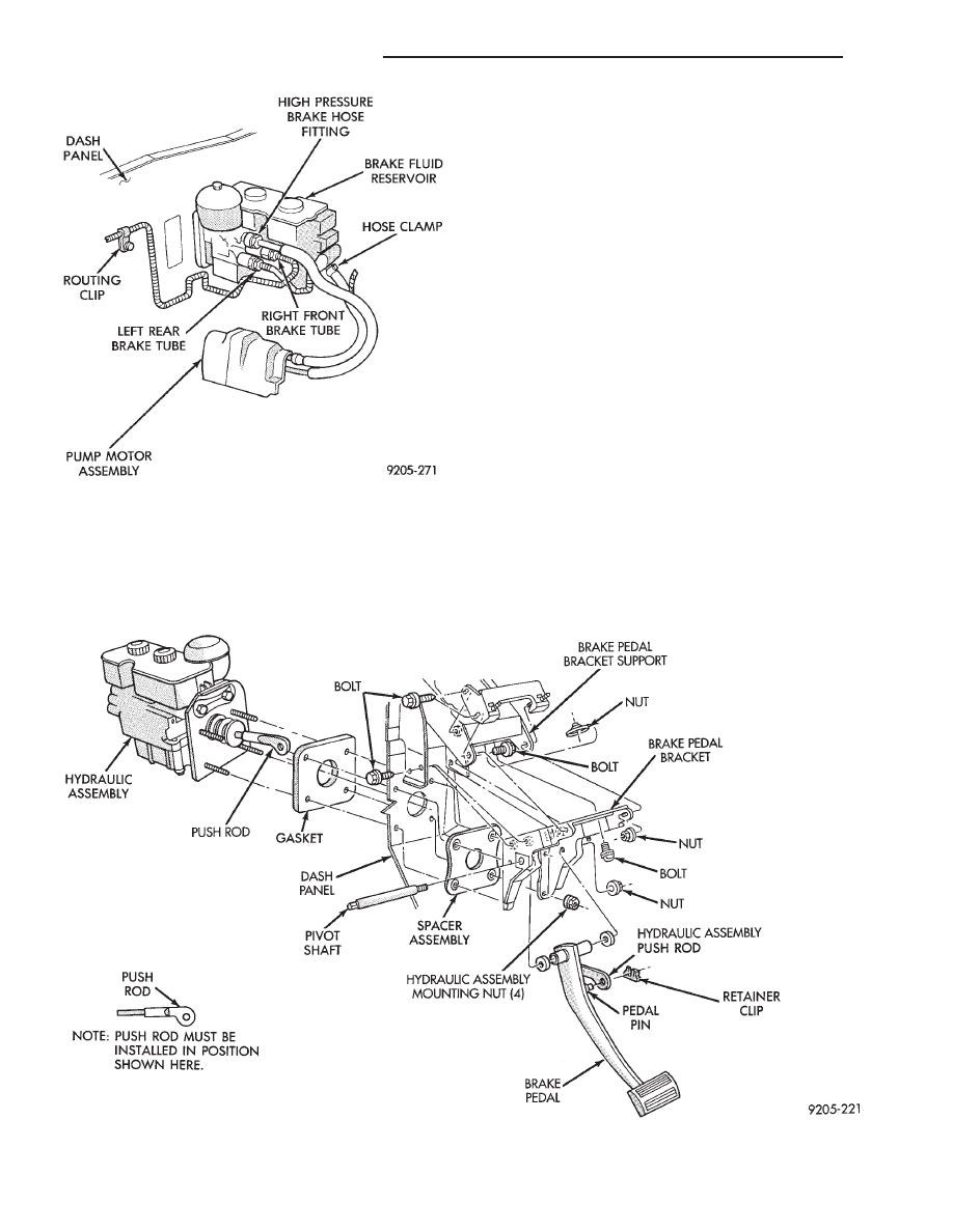
card the old retainer clip, a new clip must be
used when hydraulic assembly is reinstalled
(Fig. 8).
(10) Remove the 4 hydraulic assembly to dash
panel mounting nuts from the hydraulic assembly
mounting studs, located under instrument panel (Fig.
8).
(11) Remove hydraulic assembly from vehicle.
INSTALL
(1) Position the hydraulic assembly into its mount-
ing holes on the dash panel of the vehicle.
(2) Install and tighten the 4 hydraulic assembly to
dash panel mounting stud nuts (Fig. 8) to 28 N
Im
(250 in. lbs.) torque.
(3) Using lubriplate or equivalent, coat the bearing
surface of the brake pedal pin.
(4) Connect push rod to pedal pin and install a
NEW retainer clip. HYDRAULIC ASSEMBLY
PUSH ROD MUST BE ASSEMBLED TO BRAKE
PEDAL PIN IN THE POSITION AS SHOWN IN
(FIG. 8).
(5) If proportioning valves were removed from the
hydraulic assembly, install and torque to 40 N
Im (30
ft. lbs.) torque. Then install all 4 brake tubes on the
hydraulic assembly (Fig. 7). Torque the brake tubes
to hydraulic assembly fittings to 16 N
Im (145 in.
lbs.).
(6) Install return hose on steel tube. Tighten the
return hose clamp to 1 N
Im (10 in.lbs.)
Fig. 7 Brake Tube and Hose Routing at Hydraulic
Unit
Fig. 8 Removing or Installing Hydraulic Assembly
5 - 98
ANTI-LOCK 10 BRAKE SYSTEM
Ä