Chrysler Le Baron, Dodge Dynasty, Plymouth Acclaim. Manual - part 33
(5) Remove throttle cable. If equipped, remove the
speed control and transaxle kickdown cables.
(6) Remove return spring.
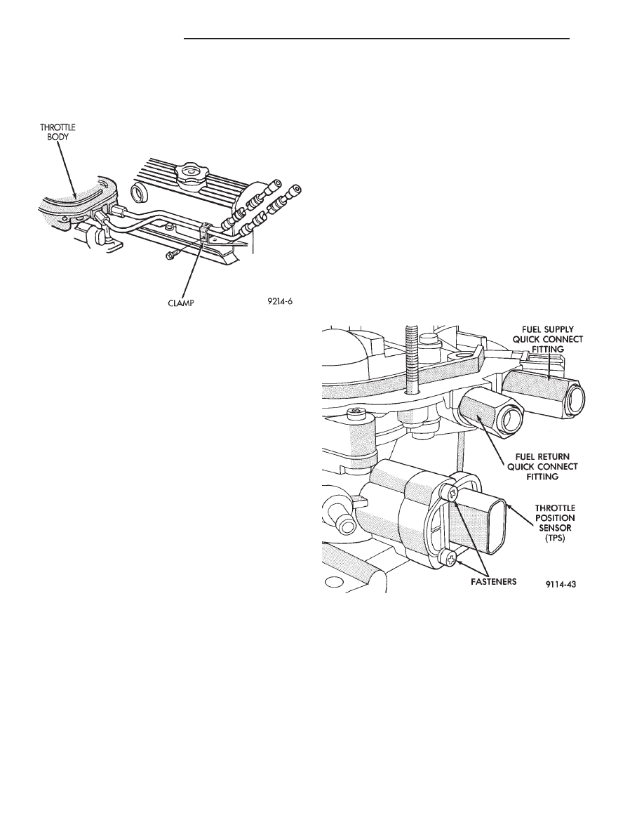
(7) Loosen fuel tube clamp on valve cover (Fig. 4).
(8) Wipe quick connect fittings to remove any dirt.
Remove fuel intake and return tubes. Refer to Fuel
Hoses, Clamps and Quick Connect Fittings in the
Fuel Delivery Section of this Group. Place a shop
towel under the connections to absorb any fuel spilled.
(9) Remove throttle body mounting screws and lift
throttle body from vehicle. Remove throttle body gas-
ket from intake manifold.
INSTALLATION
(1) Using a new gasket, install throttle body and
tighten mounting screws to 20 N
Im (175 in. lbs.)
torque.
(2) Lubricate the ends of the fuel supply and return
tubes with clean 30 weight oil. Connect fuel lines to
quick connect fittings. Refer to Fuel Hoses, Clamps
and Quick Connect Fittings in the Fuel Delivery
Section of this Group. After the fuel tubes are
connected to the fittings, pull on the tubes to ensure
that they are fully inserted and locked into position.
(3) Tighten the fuel tube clamp on the valve cover.
(4) Install return spring.
(5) Install throttle cable. If equipped, install kick-
down and speed control cables.
(6) Install wiring connectors and vacuum hoses.
(7) Install air cleaner.
(8) Reconnect negative battery cable.
CAUTION: When using the ASD Fuel System Test, the
Auto Shutdown (ASD) Relay remains energized for
either 7 minutes, until the test is stopped, or until the
ignition switch is turned to the Off position.
(9) With the ignition key in ON position, access the
DRBII scan tool ASD Fuel System Test to pressurize
the fuel system. Check for leaks.
FUEL FITTING
REMOVAL
(1) Remove air cleaner assembly.
(2) Perform Fuel System Pressure Release proce-
dure.
(3) Disconnect negative battery cable.
(4) Loosen fuel tube clamp on valve cover.
(5) Wipe any dirt from around quick connect fittings.
(Fig. 5) Place a shop towel under the connections to
catch any spilled fuel. Remove fuel tubes from quick
connect fittings. Refer to Fuel Hoses, Clamps and
Quick Connect Fittings in the Fuel Delivery Sec-
tion of this Group.
(6) Remove each fitting from throttle body and note
inlet diameter. Remove copper washers.
INSTALLATION
(1) Replace copper washers with new washers.
(2) Install fuel fittings in proper ports and tighten to
20 N
Im (175 in. lbs.) torque.
(3) Lubricate ends of the fuel tubes with 30 weight
oil. Insert the tubes into the quick connect fittings.
Refer to Fuel Hoses, Clamps and Quick Connect
Fittings in the Fuel Delivery Section of this
Group. After the fuel tubes are connected to the
fittings, pull on the tubes to ensure that they are fully
inserted and locked into position.
(4) Tighten fuel tube clamp on valve cover.
(5) Reconnect negative battery cable.
Fig. 5 Servicing Fuel Fitting
Fig. 4 Fuel Line Clamp
14 - 50
FUEL SYSTEMS
Ä