Chrysler Le Baron, Dodge Dynasty, Plymouth Acclaim. Manual - part 32
Radiator Fan Relay
A/C Clutch Relay
Auto Shutdown Relay
Purge Solenoid
S/C Servo Solenoids
Generator Field
Tachometer Output
Torque Converter Clutch Solenoid (3 speed auto-
matic transaxle only)
EGR Solenoid
All Solenoids/Relays
ASD Fuel System Test
Speed Control Vacuum Solenoid
Speed Control Vent Solenoid
THROTTLE BODY MINIMUM AIR FLOW CHECK
PROCEDURE
(1) Connect DRBII scan tool.
(2) Remove air cleaner assembly. Plug the heated
air door vacuum hose.
(3) Warm engine in Park or Neutral until the cool-
ing fan has cycled on and off at least once.
(4) Hook-up timing check device and tachometer.
(5) Disconnect the coolant temperature sensor and
set basic timing to 12°BTDC
6 2°BTDC.
(6) Shut off engine. Reconnect coolant temperature
sensor.
(7) Disconnect the PCV valve hose from the intake
manifold nipple.
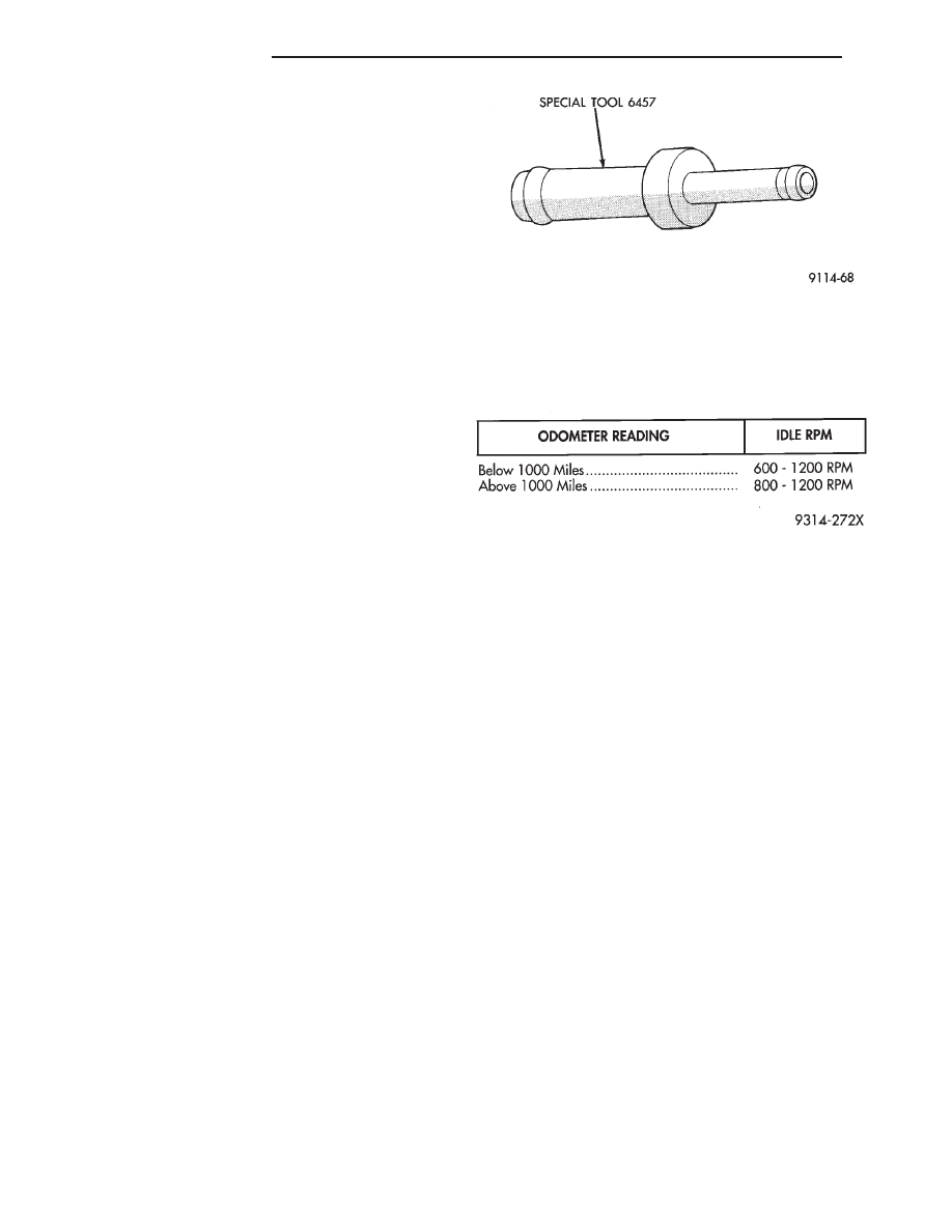
(8) Attach Air Metering Fitting #6457 (Fig. 4) to
the intake manifold PCV nipple.
(9) Restart the engine, allow engine to idle for at
least one minute.
(10) Using the DRBII scan tool, Access Min Air-
flow Idle Spd in the sensor read test mode.
(11) The following will then occur:
• Idle air control motor will fully close.
• Idle spark advance will become fixed.
• Idle fuel will be provided at a set value.
• Engine RPM will be displayed on DRBII scan tool.
(12) Check idle RPM with tachometer. If idle RPM
is within the specifications listed below, then the
throttle body minimum air flow is set correctly.
If idle RPM is not within specification replace
throttle body.
(13) Shut off engine.
(14) Remove Special Tool number 6457 from in-
take manifold PCV nipple. Reinstall the PCV valve
hose.
(15) Remove DRBII scan tool.
(16) Reinstall
air
cleaner
assembly.
Reinstall
heated air door vacuum hose.
(17) Disconnect timing check device and tachome-
ter.
IGNITION TIMING PROCEDURE
Refer to Group 8D Ignition System
60-WAY PCM WIRING CONNECTOR
Refer to the powertrain control module (PCM) wir-
ing connector descriptions for information regarding
wire colors and cavity numbers (Fig. 5).
Fig. 4 Air Metering Fitting
IDLE SPECIFICATIONS
14 - 46
FUEL SYSTEMS
Ä