Chrysler Le Baron, Dodge Dynasty, Plymouth Acclaim. Manual - part 31
once the system has entered closed loop. Refer to
Modes of Operation in this section for an explanation
of closed loop operation.
NON-MONITORED CIRCUITS
The PCM does not monitor the following circuits,
systems and conditions that could have malfunctions
that result in driveability problems. Diagnostic trou-
ble codes may not be displayed for these conditions.
However, problems with these systems may cause di-
agnostic trouble codes to be displayed for other sys-
tems. For example, a fuel pressure problem will not
register a fault directly, but could cause a rich or
lean condition. This could cause an oxygen sensor
fault to be stored in the PCM.
Fuel Pressure - Fuel pressure is controlled by the
fuel pressure regulator. The PCM cannot detect a
clogged fuel pump inlet filter, clogged in-line fuel fil-
ter, or a pinched fuel supply or return line. However,
these could result in a rich or lean condition causing
an oxygen sensor fault.
Secondary Ignition Circuit - The PCM cannot
detect an inoperative ignition coil, fouled or worn
spark plugs, ignition cross firing, or open spark plug
cables.
Engine Timing - The PCM cannot detect an incor-
rectly indexed timing chain, camshaft sprocket and
crankshaft sprocket. The PCM also cannot detect an
incorrectly indexed distributor. However, these could
result in a rich or lean condition causing an oxygen
sensor fault to be stored in the PCM.
Cylinder Compression - The PCM cannot detect
uneven, low, or high engine cylinder compression.
Exhaust System - The PCM cannot detect a
plugged, restricted or leaking exhaust system.
Fuel Injector Malfunctions - The PCM cannot
determine if the fuel injector is clogged, the pintle is
sticking or the wrong injector is installed. However,
these could result in a rich or lean condition causing
an oxygen sensor fault to be stored in the PCM.
Excessive Oil Consumption - Although the PCM
monitors the exhaust stream oxygen content through
the oxygen sensor when the system is in closed loop,
it cannot determine excessive oil consumption.
Throttle Body Air Flow - The PCM cannot detect
a clogged or restricted air cleaner inlet or filter ele-
ment.
Evaporative System - The PCM will not detect a
restricted, plugged or loaded evaporative purge can-
ister.
Vacuum Assist - Leaks or restrictions in the vac-
uum circuits of vacuum assisted engine control sys-
tem devices are not monitored by the PCM. However,
these could result in a MAP sensor fault being stored
in the PCM.
PCM System Ground - The PCM cannot deter-
mine a poor system ground. However, a diagnostic
trouble code may be generated as a result of this con-
dition.
PCM Connector Engagement - The PCM cannot
determine spread or damaged connector pins. How-
ever, a diagnostic trouble code may be generated as a
result of this condition.
HIGH AND LOW LIMITS
The powertrain control module (PCM) compares in-
put signal voltages from each input device with es-
tablished high and low limits that are programmed
into it for that device. If the input voltage is not
within specifications and other diagnostic trouble
code criteria are met, a diagnostic trouble code will
be stored in memory. Other diagnostic trouble code
criteria might include engine RPM limits or input
voltages from other sensors or switches that must be
present before a fault condition can be verified.
DIAGNOSTIC TROUBLE CODE DESCRIPTION
When a diagnostic trouble code appears, it indi-
cates the powertrain control module (PCM) has rec-
ognized
an
abnormal
condition
in
the
system.
Diagnostic trouble codes can be obtained from the
malfunction indicator lamp (instrument panel Check
Engine lamp) on the Instrument Panel or from the
DRBII scan tool. Diagnostic trouble codes indicate
the results of a failure but do not identify the failed
component directly.
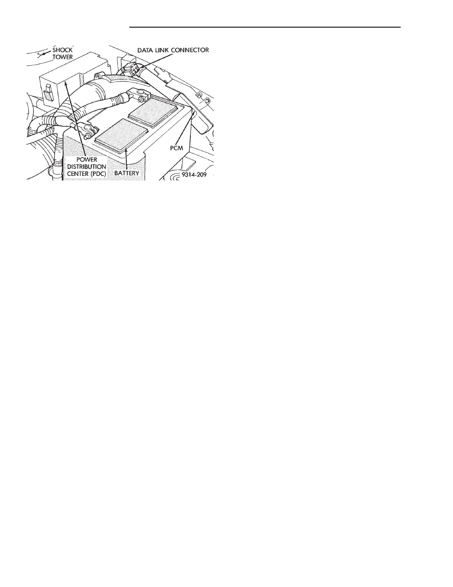
Fig. 3 Data Link Connector Location—AG and AJ
Vehicles
14 - 42
FUEL SYSTEMS
Ä