Daewoo Musso. Manual - part 315


  Index      Daewoo     Daewoo Musso - service repair manual


Search            


Content   ..  313  314  315  316   ..


Daewoo Musso. Manual - part 315


POWER STEERING SYSTEM  6A-9

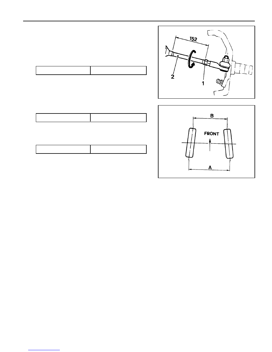
Inspection Procedure

1. Check the distance of tie rod and toe-in data and, if

necessary, adjust as below.

2. Adjustment

l

Unscrew the adjuster nut (1) and adjust the distance by

turning the rod (2) counterclockwise.

Distance of Tie Rod

152mm

Toe-in

0 - 4 mm

Tightening  Torque

65 - 80Nm

l

Check the toe-in date (A~B)

l

If the ton-in is normal, tighten the adjuster nut (1) to the

specified toque with tie rod (2) being fixed.

Tightening

SECTION 6E

STEERING  WHEEL  AND  COLUMN

TABLE OF CONTENTS

Specification . . . . . . . . . . . . . . . . . . . . . . . .  6E-1

Fastener  Tightening  Specifications . . . . . . . . .  6E-1

Maintenance and Repair . . . . . . . . . . . . . . .  6E-2

SPECIFICATIONS

FASTENER TIGHTENING SPECIFICATIONS

Application

Steering Wheel Mounting Nut

Steering Lower Shaft Bolt

Steering Column Shaft Bolt

Steering Column Mounting Bolt

N

l

m

50 - 80

30 - 40

9 - 14

15 - 20

On-Vehicle Service . . . . . . . . . . . . . . . . . . . . . .  6E-2

Steering Column . . . . . . . . . . . . . . . . . . . . . . .  6E-2

6E-2  STEERING WHEEL AND COLUMN

MAINTENANCE AND REPAIR

ON-VEHICLE SERVICE

STEERING COLUMN

1 Horn Pad
2 Nut ....................................................... 50-80 Nm
3 Washer
4 Steering Wheel
5 Combination Switch Assembly
6 Combination Switch Lower Cover
7 Combination Switch Upper Cover
8 Bolt
9 Bolt

10 Bolt

11 Crash Pad Panel

12 Bolt ...................................................... 30-40 Nm
13 Spring Washer
14 Steering Column Shaft
15 Bolt ........................................................ 9-14 Nm
16 Bolt ...................................................... 13-40 Nm
17 Column & Shaft Assembly

STEERING WHEEL AND COLUMN  6E-3

Removal & Installation Procedure

1. Remove the horn pad from the steering wheel and

disconnect the connectors .

2. Place an alignment marks on the column shaft end and

fixing nut and then remove the fixing nut.

Installation Notice

3. Remove the steering wheel.

4. Remove the combination switch upper cover .

Tightening  Torque

50 - 80 Nm

5. Release the crash pad panel.

Notice

Remove the hood release wire and the other switch
connectors.


Content   ..  313  314  315  316   ..