Daewoo Matiz (2003 year). Manual - part 159


  Index      Daewoo     Daewoo Matiz - service repair manual 2003 year


Search            


Content   ..  157  158  159  160   ..


Daewoo Matiz (2003 year). Manual - part 159


FIVE-SPEED MANUAL TRANSAXLE  5B – 19

D13B530A

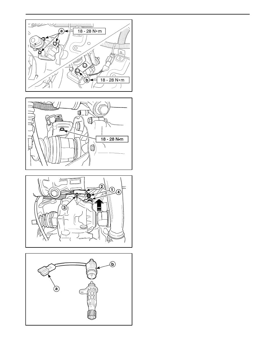
3. Install the gear shift control case and the select lever.

Tighten

D

Tighten the gear shift control case bolts to 18–28
N

S

m (13–21 lb-ft).

a. Gear shift control case bolt.

D

Tighten the select lever bolts to 18–28 N

S

m (13–21

lb-ft).

b. Select lever bolt.

Important: Make sure a correct bolt. There is length dif-
ference between select lever bolts.

D13B531A

4. Install the shift interlock bolt.

Tighten

Tighten the shift interlock bolt to 18–28 N

S

m (13–21

lb-ft).

D103B532

SPEEDOMETER DRIVEN GEAR AND
CABLE

(Left–Hand Drive Shown, Right–Hand
Drive Similar)

Removal Procedure

1. Remove the speedometer driven gear assembly.

D

Loosen the nut. (1).

D

Disconnect the cable (2).

D

Remove the bolt (3).

D

Remove the speedometer driven gear assembly
(4).

D103B533

D

Disconnect the vehicle speed sensor connector (If
equipped).

a. Vehicle speed sensor connector.

D

Disconnect the vehicle speed sensor.

b. Vehicle speed sensor.

Caution: Be careful to prevent personal injury while
the exhaust pipe is hot.

5B – 20  FIVE-SPEED MANUAL TRANSAXLE

D103B534

2. Remove the battery. Refer to Section 1E, Engine

Electrical.

3. Disconnect the instrument cluster side cable. Refer to

Section 9E, Instrumentation/Driver Information.

4. Remove the speedometer cable.

D

Remove the cable grommet (1).

D

Pull out the speedometer cable from the dash pan-
el.

D103B535

Inspection Procedure

1. Remove the O–ring from the speedometer driven

gear housing.

2. Remove the driven gear pin and disconnect the driv-

en gear.

D

Check for a damaged or torn O–ring.

D

Check for a worn or damaged tooth of driven gear.

a. O–ring.

b. Driven gear pin.

c. Driven gear.

D103B536

Installation Procedure

1. Install in the reverse order of removal.

Important: Install the speedometer driven gear assem-
bly after connecting the speedometer cable with the
speedometer driven gear assembly completely.

D13B537A

2. Install the speedometer driven gear assembly to

transaxle housing.

Tighten

Tighten the speedometer driven gear assembly bolt
to 4–7 N

S

m (35–62 lb-in).

FIVE-SPEED MANUAL TRANSAXLE  5B – 21

D103B501

GEAR SHIFT CONTROL CABLE

Removal Procedure

1. Remove the air hose (air cleaner to throttle body).

Refer to Section 1B, SOHC Engine Mechanical.

2. Remove the battery.

3. Disconnect the transaxle side select and shift control

cable.

D

Remove the cable pins (1).

D

Remove the washers (2).

D

Disconnect the select and shift control cable (3).

D

Remove the cable E–rings (4).

D

Disconnect the cables from the cable bracket.

D19E573A

4. Remove the floor console. Refer to Section 9G, Inte-

rior Trim.

D

Put aside the floor carpet in order to get the gear
shift cable shown.

D13B5381

5. Disconnect the gear shift lever side select and shift

control cable.

D

Remove the select control cable clip (1).

D

Ply off the eye ring (2).

D

Remove the select control cable E–ring (3).

D

Disconnect the select control cable (4).

D

Remove the shift control cable pin (5).

D

Remove the shift control cable E–ring (6).

D

Ply off the shift control cable (7).

D13B539A

6. Remove the select and shift control cable.

D

Remove the nuts (1).

D

Pull the cables out in the passenger room.

5B – 22  FIVE-SPEED MANUAL TRANSAXLE

D103B540

Installation Procedure

1. Install in the reverse order of removal.

2. Push the cables toward the engine compartment

through dash panel’s hole slightly.

3. Position the cables on the select and the shift lever.

D13B5411

4. Connect the transaxle side select and shift control

cable.

5. Connect the gear shift lever side shift control cable.

6. Connect the gear shift lever side select control cable.

D

Insert the select control cable eye ring to the select
arm pin (1).

D

Install the selector lever control cable clip (2).

D

Install the select control cable to gear shift lever
bracket with E–ring (3).

D

Insert a driver to the select arm adjustment hole to
prevent the movement of gear shift lever in NEU-
TRAL (4).

7. Tighten the adjust nuts.

Tighten

Tighten the select cable adjust nut to 8–12 N

S

m

(71–106 lb-in).

D103B543

GEAR SHIFT CONTROL LEVER

Removal Procedure

1. Remove the floor console. Refer to Section 9G, Inte-

rior Trim.

2. Disconnect the select and shift control cable. Refer to

“Gear Shift control cable” in this section.

3. Remove the gear shift control lever assembly.

D

Remove the bolts (1).

D

Remove the gear shift control lever assembly (2).

D

Remove the gear shift lever sensor connector.
(If equipped with auto clutch).


Content   ..  157  158  159  160   ..