Daewoo Matiz (2003 year). Manual - part 158
 

  Index      Daewoo     Daewoo Matiz - service repair manual 2003 year


Search            


Content   ..  156  157  158  159   ..


Daewoo Matiz (2003 year). Manual - part 158


FIVE-SPEED MANUAL TRANSAXLE  5B – 15

D13B518A

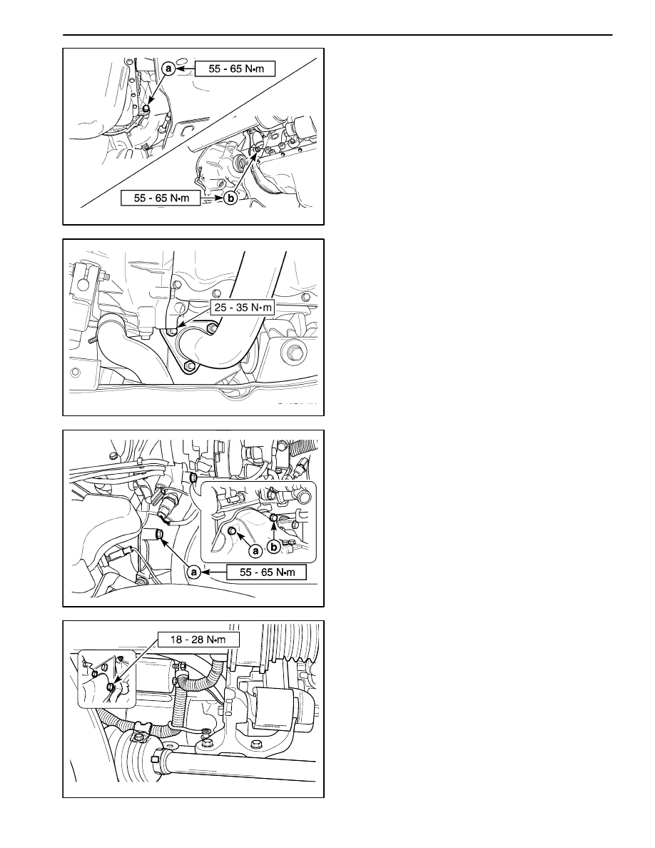
3. Install the transaxle lower bolt, nut.

Tighten

Tighten the bolt and nut to 55–65 N

S

m (41–48 lb-ft).

a. Lower bolt.

b. Lower nut.

D13B5472

4. Tighten the front exhaust pipe nuts.

Tighten

D

Tighten the front exhaust pipe nuts (exhaust man-
ifold side) to 25–35 N

S

m (18–25 lb-ft).

D13B519A

5. Install the transaxle upper bolts.

Tighten

Tighten the bolts to 55–65 N

S

m (41–48 lb-ft).

a. Exhaust manifold side bolt.

b. Thermostat housing side bolt.

D13B548A

6. Install the starter motor.

Tighten

Tighten the starter motor bolts to 18–28 N

S

m (13–21

lb-ft).

7. Connect all electric connectors.

5B – 16  FIVE-SPEED MANUAL TRANSAXLE

D13B5032

8. Install the radiator lower hose and crank position

(CKP) sensor.

Tighten

Tighten the radiator lower hose bolt to 8–15 N

S

m

(70–132 lb-in).

Tighten the CKP sensor bolt to 5–8 N

S

m (44–70 lb-

in).

D13B520A

9. Refill the transaxle fluid.

D

Tighten the drain plug to 25–30 N

S

m (18–22 lb-ft)

(a).

D

Remove the oil level plug (1).

D

Refill recommended fluid to the proper level.

ÁÁÁÁÁÁÁÁÁ

ÁÁÁÁÁÁÁÁÁ

Classification

ÁÁÁÁÁÁÁÁÁ

ÁÁÁÁÁÁÁÁÁ

75W – 85 (GL–4)

ÁÁÁÁÁÁÁÁÁ

ÁÁÁÁÁÁÁÁÁ

Capacity

2.1L (2.21 qt)

D

Tighten the oil level plug to 36–54 N

S

m (26–40 lb-ft)

(b).

D13B521A

10. Adjust the clutch cable. Refer to Section 5C, Clutch.

D

Adjust the clutch cable by the clutch cable adjust
nut.

11. Install the transaxle under cover.

Tighten

Tighten the transaxle under cover bolts to 35–55
N

S

m (25–41 lb-ft).

D103B501

GEAR SHIFT CONTROL CASE
ASSEMBLY

Removal Procedure

1. Remove the air hose (air cleaner to throttle body).

Refer to Section 1B, SOHC Engine Mechanical.

2. Remove the battery.
3. Disconnect the select and the shift control cable.

D

Remove the cable pins (1).

D

Remove the washers (2).

D

Disconnect the select and the shift control cable
(3).

D

Remove the cable E–rings (4).

D

Disconnect the cables from the cable bracket.

FIVE-SPEED MANUAL TRANSAXLE  5B – 17

D103B522

4. Remove the select lever.

D

Remove the bolts (1).

D

Remove the select lever (2).

D103B523

5. Remove the shift interlock bolt.

Important: Certainly remove the shift interlock bolt.
Otherwise, the gear shift control case can not be re-
moved.

D103B524

6. Remove the gear shift control case assembly.

D

Remove the bolts (1).

Important: Make sure the gear shift lever is in NEU-
TRAL.

D

Remove the gear shift control case assembly (2).

D

Remove the gasket (3).

D103B525

7. Remove the shift lever.

D

Position the gear shift control case assembly to the
vice with a protector.

D

Remove the lever pin with a pin punch and a ham-
mer (1).

D

Remove the shift lever (2).

D

Remove the boot (3).

5B – 18  FIVE-SPEED MANUAL TRANSAXLE

D103B526

8. Remove the select/shift shaft.

D

Remove the shift guide bolt (1).

D

Remove the select/shift shaft (2).

D103B527

9. Remove the gear shift control case plate.

D

Remove the bolts (1).

D

Remove the Plate from the case (2).

D103B528

Inspection Procedure

1. Inspect for worn or damaged the fifth/reverse shift

cam (1).

2. Inspect for worn or damaged shift interlock plate (2).

3. Inspect for worn or damaged select/shift lever (3).

4. Inspect for bent or damaged select/shift shaft (4).

D13B529A

Installation Procedure

1. Install in the reverse order of removal.

2. Install the shift guide bolt.

Tighten

Tighten the shift guide bolt to 18–28 N

S

m (13–21 lb-ft).


Content   ..  156  157  158  159   ..