Citroen Xsara Picasso (2005 year). Instruction - part 7


  Index      Citroen     Citroen Xsara Picasso - instruction 2005 year in english


Search            


Content   ..  5  6  7  8   ..


Citroen Xsara Picasso (2005 year). Instruction - part 7


103

IV

IV

F U S E S

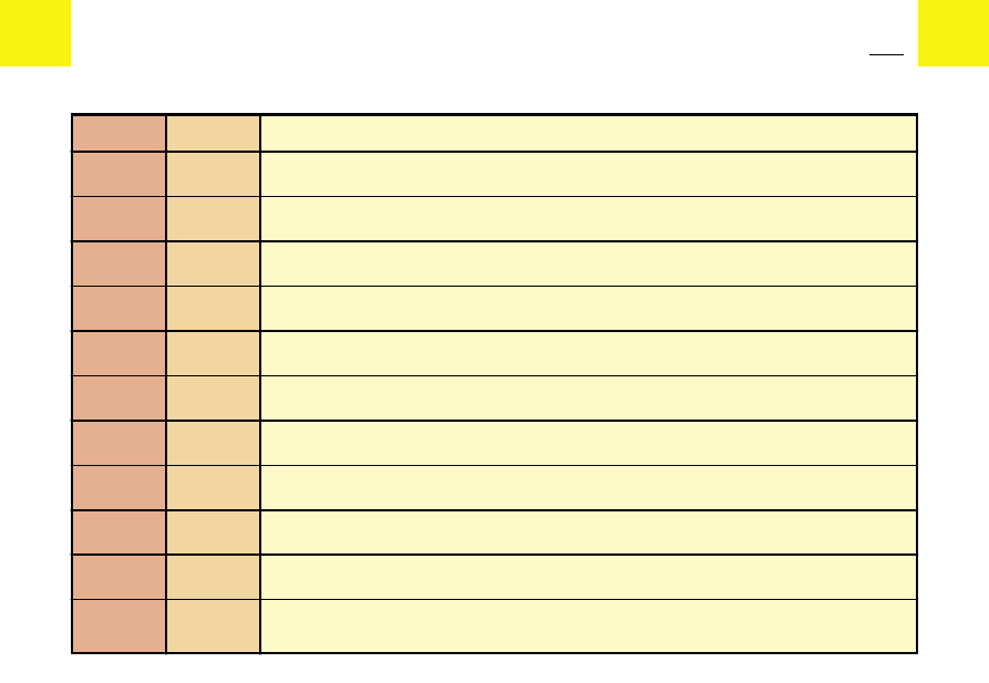
Fuses under the dashboard

Number

Rating

Functions

F1

15 A

Diagnostic socket - Caravan towbar

F2

-

Unused

F3

-

Unused

F4

20 A

ECU Navigation system - Instrument panel - Audio system - Diesel fuel additive system - Controls at the steering wheel

F5

15 A

-

F6

10 A

Diagnostic socket

F7

15 A       Rain and sunlight sensor

F8

-

Unused

F9

30 A

Sun roof - Electric rear windows

F10

40 A

Heated rear screen - Demisting rear view mirror

F11

15 A

Rear screen wiper

104

IV

IV

F U S E S

Number

Rating

Functions

F12

30 A

Electric front windows

F13

-

Unused

F14

10 A       Controls at the steering wheel - Diesel fuel additive system - Airbags - Parking assistance 

F15

15 A       Instrument panel - Radio - Air conditioning - Navigation

F16

30 A

Central locking

F17

-

Unused

F18

-

Unused

F19

-

Unused

F20

10 A

Right hand stoplamp

F21

15 A

Left hand stoplamp

F22

20 A

Interior lamp - Cigar lighter - 12V socket - Glovebox lighting

1

3

2

8

15

16

17

7

4

9 10

11 12 13 14

18

5

6

IV

IV

F U S E S

Fuses under the bonnet

Fuse box
To reach the fuses in the fusebox

under the bonnet unclip the cover.

Close the lid of the fuse box

carefully.

Only authorised personnel from the CITROËN network

are allowed to carry out any work on the additional protection

MAXI fuses located in the fuse boxes.

105

IV

IV

F U S E S

Fuses under the bonnet

Number

Rating

Functions

F1

10 A       Reversing lamp - Water-in-diesel-fuel sensor - Coolant 

F2

15 A

Fuel pump

F3

10 A

ABS ECU

F4

10 A

Engine ECU - Automatic gearbox ECU

F5

10 A       Automatic gearbox - Diesel fuel additive system

F6

15 A

Front foglamps

F7

15 A

Automatic lighting

F8

20 A

Engine ECU

F9

15 A

Left hand dipped beam

106

IV

IV

F U S E S

Number

Rating

Functions

F10

15 A

Right hand dipped beam

F11

10 A

Left hand main beam

F12

10 A

Right hand main beam

F13

15 A

Warning

F14

10 A

Windscreen/rear screen wash pump

F15

30 A       Engine sensors, ignition coils, injectors, Electrovalves

F16

30 A

Air pump

F17

30 A

Windscreen wiper

F18

40 A

Air conditioning blower

107


V

V

F u e l

Locking filler cap
Turn the key a quarter turn to lock

and unlock the filler cap.
When refuelling, place the cap in

the support provided on the inside

of the filler flap.

For petrol engines with catalytic converter, use of unleaded fuel is ob-

ligatory
The filler neck has a narrower aperture to permit unleaded petrol only.

If you are filling up with fuel, do not persist in topping up after the third

cut- off; this could cause your vehicle to malfunction.

Tank capacity (litres):
- 55 Approximately (Petrol models:).
- 60 Approximately (Diesel models:).

FUEL QUALITY
A label on the inside of the fuel filler flap indicates the approved fuel quality

type.

UNLEADED PETROL

DIESEL FUEL

Petrol engines are designed to run on RON 95 fuel; however, for better vehi-

cle performance (petrol engines), we recommend RON 98.

If you have put in fuel that is wrong for your vehicle, it is essen-

tial to have the tank drained before you start the engine.

108

1

3

2

V

V

R E P L A C I N G B U L B S

Headlamp

Headlamp dipped beam /

Main beam

Sidelamp

Direction indicator

Note: A light mist of condensation

may appear on the surface of the

headlamp glass under certain con-

ditions of use.

Headlamp dipped beam /

Main beam
Disconnect the connector, remove

the rubber protector.
Press and release the slides.
Remove the bulb- holder.

Bulb: H4 (anti U.V.).

Sidelamp:
Rotate the bulb-holder a quarter

turn and pull.

Bulb: W 5 W.

The halogen bulbs should not be changed until they have been off

for a few minutes (risk of serious burns). Do not touch the new bulb

directly with your fingers; use a lint-free cloth.
It is essential that only anti- U.V. type bulbs are used in order not to

damage the headlamp.

109

V

V

R E P L A C I N G B U L B S

Front direction indicator
Rotate the bulb-holder a quarter

turn and pull.
Reconnect and refit the direction in-

dicator in its housing, engaging the

tabs in their guides

Bulb: PY 21 W.

Side repeater direction indica-

tor
Push the unit forwards or towards

the rear to unclip it, then pull it to-

wards you.
Turn the bulb holder a quarter of a

turn.

Bulb: PY 5 W.

Front foglamps
Contact your CITROËN dealer.

Bulb: H1.

110

V

V

R E P L A C I N G B U L B S

Interior lamp
Unclip the cover to gain access to

the bulb.

Bulb: W 6 W (N3 xénon).

Boot lighting
Unclip the lens cover then pull out

the bulb holder.

Bulb: W 5 W.

Glovebox lighting
Unclip the cover to gain access to

the bulb.

Bulb: W 5 W.

111

1

2

3

4

V

V

R E P L A C I N G B U L B S

Rear lamp unit
Identify the failed bulb

Bulbs:

Stop lamps

and sidelamps:

P 21/5 W.

Direction indicator:PY 21 W.

Reversing lamp:

P 21 W.

foglamp:

P 21 W.

Removal
In the side storage compartment,

remove the trim covering the ac-

cess to the lamps.
- release the bottom of the lamp

unit by pressing the lower retain-

ing spring. (with a tool such as a

screwdriver, if necessary).

From outside:
- pull the unit downwards to release

the upper retaining spring,

- remove

the

bulb-

holder

by

squeezing the tabs,

- replace the faulty bulb.

To refit
Engage the top of the unit in order

to fix the upper retaining spring,

and press on the bottom of the unit

to clip the lower retaining spring.

112

V

V

R E P L A C I N G B U L B S

Third stop lamp
Open the tailgate and remove the

cap to reach the bulb.

Bulb: W 5 W (5 Bulbs).

Rear number plate lamp
Unclip the lens cover.

Bulb: W 5 W.

After replacing a bulb, check the correct operation

of the lighting and signalling.

113

A

V

V

T o w b a r

Dimensions (in metres): 0.792.

Towbar
The installation of a towbar should be carried out by a CITROËN dealer, who

will be aware of the towing capacity of your vehicle, has information on the fit-

ting procedure as well as any modifications to the cooling system needed to

cater for the intended towing conditions.

Towing (a caravan or boat etc.)
If the vehicle is climbing a steep incline or the engine is overheating, certain

functions become unavailable (automatic gearbox sequential control, air

conditioning).

Towing advice

When towing a trailer with a fully

laden vehicle, restrict your speed to

a maximum of 60 mph.
Vehicle performance reduces with

altitude. At altitudes of 1,000 me-

tres, and for every additional 1,000

metres,

the

maximum

towing

weight should be reduced by

100kg.

114

V

V

R O O F B A R S

Roof bars
Both for your safety and to avoid damage to its roof, your vehicle is designed for the use of roof bars that are specifical-

ly tested and approved by the CITROËN network.

Recommendations
• Spread the load evenly, avoid overloading one side.
• Keep heavy objects at the bottom of the load.
• Strap the load securely, and signal any overhanging load.
• Drive gently, the effect of side winds will be increased.
• Remove the roof rack or roof bars when not in use.

Respect the authorised load capacities.

For maximum loads that can be distributed on the roof bars.

See Chapter: “General information”.

115

A

B

2

3

4

1

A

2

3

4

1

V

V

C O L D W E A T H E R G R I L L E

( S n o w g u a r d )

Instructions for fitting the snow

guard:
- Clip component on the bumper

rib at A.

- Position the snow guard 2, first

engaging the lug on the bumper

rib at B.

- Secure the snow guard by tight-

ening screw into component 1.

The snow-guard grille should on-

ly be fitted during the winter peri-

od. It should be removed for the

rest of the year.

It is essential to remove the

snow-guard grille whenever tem-

peratures rise above 10°C.

116

1

2

V

V

C H A N G I N G A W H E E L

Tools
The wheelbrace is clipped into

the cover of the stowage area

located under the floor behind one

of the front seats.
The jack and its handle are located

in a protective holder in the spare

wheel under the boot floor.
Pull it upwards to release.
The anti- theft wheel bolt sockets

are stowed in the glovebox.

Access to the spare wheel
The wheel carrier retaining bolt is

situated under the boot carpet near

the tailgate catch.
Unscrew the retaining bolt using

the end of the wheel brace.
Lift the carrier to disengage the

hook, and lower the carrier.

Never get underneath the

vehicle if it is supported on-

ly by the jack.

Removal
1 - Park the vehicle on stable, firm ground. Apply the handbrake.Switch off

the ignition and engage first gear or reverse gear, depending on any

slope (for vehicles with automatic gearbox, select position P).
Place the chock (1), integrated in the protective holder, behind the

wheel diagonally opposite that being changed. See the label in-

side the cover of the chock protective holder.

2 - Position the jack at one of the four jacking points on the underside of the

vehicle adjacent to the wheels. Using the wheel brace, extend the jack

until it touches the ground

3 - To remove the embellisher, pull on one of the holes in the embellisher us-

ing the end of the wheel brace.

4 - Loosen the wheel bolts using the wheel brace.
5 - Extend the jack until the wheel is a few centimetres off the ground.
6 - Unscrewing the wheel bolts and remove the wheel.

117

2

V

V

C H A N G I N G A W H E E L

Wheels with aluminium rims
Remove the embellisher conceal-

ing the four wheel bolts, using the

curved end of tool contained in

the protection box to be found in-

side the spare wheel.

Anti- theft bolts
Each wheel has one anti-theft bolt.

To remove this bolt, use one of the

two anti-theft sockets (given to you

at the time of delivery of your vehi-

cle along with duplicate keys and

confidential card) and the wheel-

brace.

Note: take care to note down the

code number engraved on the

head of the anti- theft bolt socket. It

will enable you to obtain a duplicate

anti-theft

bolt

socket

from

a

CITROËN dealer.

Spare wheel
Your vehicle is equipped with a

steel spare wheel: when fitting it, it

is normal to observe that the base

of the wheel bolt does not come to

bear on the wheel rim.
The spare wheel is secured by the

conical tapering on the shaft of

each wheel bolt.
When refitting the original wheel,

ensure that the bases of the wheel

bolts are in a clean condition.

To refit
1 - Fit the wheel onto the hub, making sure that it is correctly positioned.
2 - Screw in the bolts but do not fully tighten them.
3 - Lower the jack and remove it.
4 - Using the wheel brace, fully tighten the wheel bolts,.
5 - Refit the wheel embellisher, aligning the tyre valve aperture with the valve,

then pressing it home around its circumference.

6 - As soon as possible, have the tyre repaired and the original wheel refit-

ted.

7 - Make sure the tyre is inflated to the correct pressure (see “Vehicle identifi-

cation” and “User precautions”). Have the wheel balanced.

118


Content   ..  5  6  7  8   ..