Chrysler RG Voyager. Manual - part 987
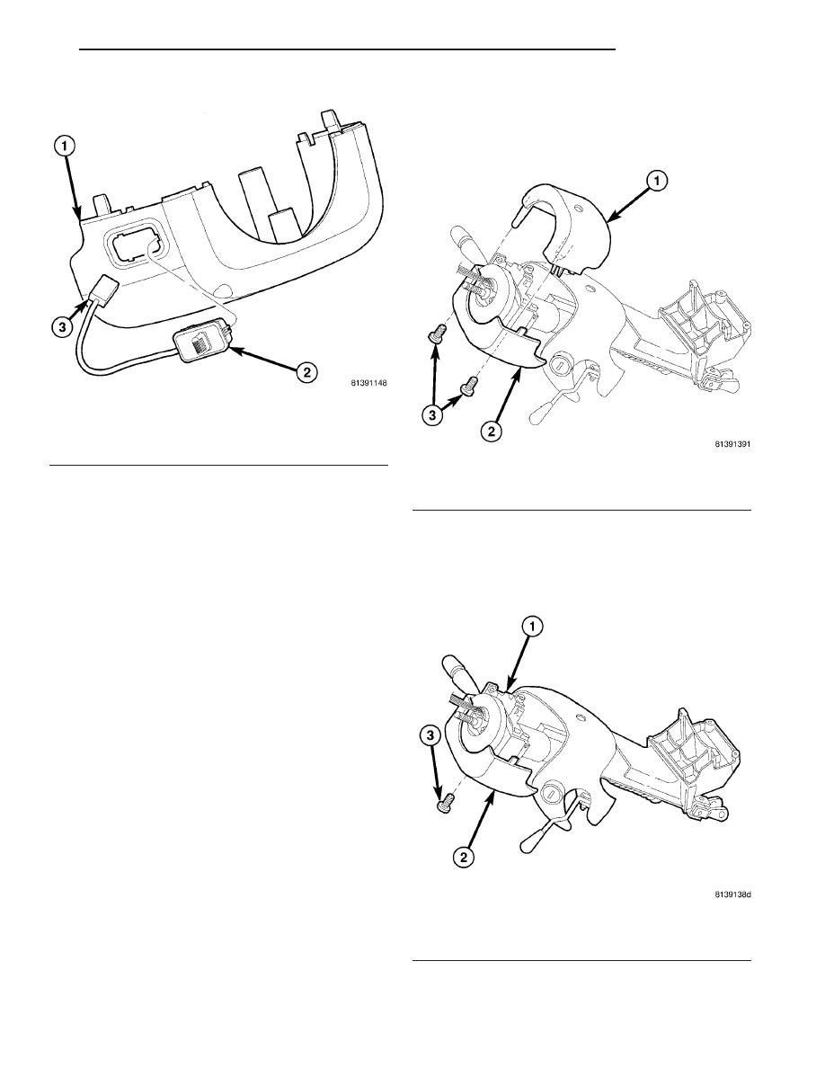
(4) If equipped with adjustable pedals, disconnect
the wiring connector for the switch (Fig. 34).
(5) Remove the lower shroud from the steering col-
umn.
(6) If equipped with adjustable pedals, depress the
retaining tabs on the switch and remove the switch
from the lower shroud (Fig. 34).
INSTALLATION
(1) If the vehicle is equipped with adjustable pedals:
(a) Pass the wiring through the mounting hole
and install the switch into the lower shroud (Fig.
34), snapping it into place.
(b) Connect the switch wiring connector to the
column wiring harness.
(2) Position the lower shroud under the steering
column
and
install
the
lower
shroud-to-column
mounting screw (Fig. 33). Tighten the screw to 2 N·m
(17 in. lbs.) torque.
(3) Align the upper shroud with the lower, then
snap shrouds together at locking tab locations on
both sides of column.
(4) Install
the
two
shroud-to-shroud
mounting
screws (Fig. 32). Tighten the screws to 2 N·m (17 in.
lbs.) torque.
(5) Inspect shroud mating surfaces for excessive
gaps and correct as necessary.
(6) Check operation of any previously disconnected
switches.
SHROUD - UPPER
REMOVAL
(1) Remove
the
two
shroud-to-shroud
mounting
screws fastening the upper to lower shrouds (Fig. 35).
(2) Using hands on each side of the column, gently
press inward at seams between the two shrouds at
points of contact to disengage inner locking tabs.
Fig. 34 Adjustable Pedals Switch Mounting
1 - LOWER SHROUD
2 - ADJUSTABLE PEDALS SWITCH
3 - WIRING CONNECTOR
Fig. 35 Upper Shroud Mounting
1 - UPPER SHROUD
2 - LOWER SHROUD
3 - MOUNTING SCREWS
Fig. 36 Lower Shroud Mounting
1 - STEERING COLUMN
2 - LOWER SHROUD
3 - MOUNTING SCREW
RS
COLUMN
19 - 23
SHROUD - LOWER (Continued)