Chrysler RG Voyager. Manual - part 986
SPECIFICATIONS
COLUMN FASTENER TORQUE
DESCRIPTION
N·m
Ft.
Lbs.
In.
Lbs.
Driver Airbag Mounting
Screws
10
—
90
Multi-Function Switch
Mounting Housing
Set-Screw
14
—
124
Shroud Attaching Screws -
Fixed
3
—
23
Shroud Attaching Screws -
Lower/Upper
2
—
17
SKIM Attaching Screw
4
—
30
Steering Column Coupling
Pinch Bolt
28
—
250
Steering Column Mounting
Nuts
12
—
105
Steering Wheel Retaining
Bolt
61
45
—
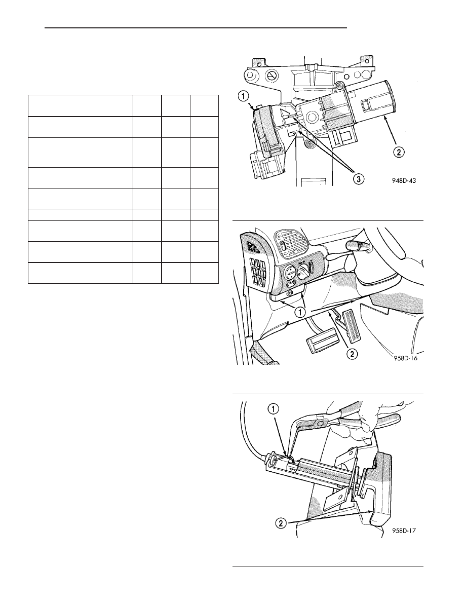
IGNITION SWITCH
REMOVAL
The ignition switch attaches to the lock cylinder
housing on the end opposite the lock cylinder (Fig.
20). For ignition switch terminal and circuit identifi-
cation, refer to the appropriate wiring information.
The wiring information includes wiring diagrams,
proper wire and connector repair procedures, further
details on wire harness routing and retention, as well
as pin-out and location views for the various wire
harness connectors, splices and grounds.
(1) Disconnect negative cable from battery.
(2) Remove steering column cover retaining screws
(Fig. 21).
(3) Remove parking brake release cable from han-
dle (Fig. 22).
Fig. 20 Ignition Switch—Viewed From Below Column
1 - IGNITION SWITCH
2 - LOCK CYLINDER HOUSING
3 - RETAINING TABS
Fig. 21 Steering Column Cover
1 - SCREWS
2 - STEERING COLUMN COVER
Fig. 22 Parking Brake Release Cable
1 - PARKING BRAKE CABLE
2 - PARKING BRAKE HANDLE
RS
COLUMN
19 - 19
COLUMN (Continued)