Chrysler RG Voyager. Manual - part 727
REMOVAL
(1) Disconnect and isolate the battery negative
cable.
(2) Remove the three retaining screws.
(3) Disconnect the central wiring harness connec-
tor from the headlamp unit.
(4) Remove the headlamp unit from the vehicle by
rotating the turn signal area out and towards the
center of the vehicle.
INSTALLATION
(1) Connect the wiring harness to the headlamp
unit’s central connector.
(2) Place the headlamp unit in the headlamp unit
pocket in front end first by placing the inboard side
behind the fascia. Complete the installation by rotat-
ing the turn signal area of the headlamp into place.
(3) Place headlamp unit into headlamp unit pocket
in front end.
(4) Install the three retaining screws.
(5) Connect the battery negative cable.
(6) Verify vehicle and system operation.
LICENSE LAMP
REMOVAL
(1) Disconnect and isolate the battery negative
cable.
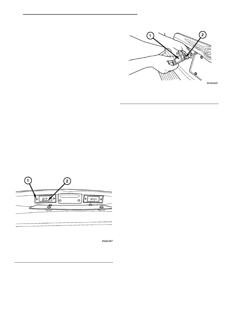
(2) Remove two screws (Fig. 18).
(3) Twist bulb socket and remove (Fig. 19).
(4) Pull bulb from socket.
INSTALLATION
(1) Push bulb into socket.
(2) Install socket into lamp.
(3) Install two screws.
(4) Reconnect the battery negative cable.
MULTI-FUNCTION SWITCH
DESCRIPTION - TURN SIGNAL SYSTEM
The turn signals are actuated with a lever on
Multi-Function Switch, located on the left side of the
steering wheel. The signals are automatically turned
off by a canceling cam (two lobes molded to the clock
spring mechanism). The cam comes in contact with
the cancel actuator on the turn signal (multi-func-
tion) switch assembly. Either cam lobe, pushing on
the cancel actuator, returns the switch to the OFF
position. The multi-function switch is a resistive
MUX switch that feeds inputs to the BCM.
OPERATION - TURN SIGNAL SYSTEM
Lane change signaling is actuated by applying par-
tial turn signal stalk movement toward the direction
desired until the indicator lamps flashes in the
instrument cluster. When the switch stalk is released
the stalk will spring back into the neutral position
turning OFF the turn signal.
With the ignition switch ON and the turn signal
switch stalk actuated left or right, current flows
through the:
• Multi-function switch
• Body Control Module
• Integrated Power Module (IPM)
• Turn indicator lamp
• Front and rear turn signal bulbs.
A chime will sound after the vehicle has traveled a
distance of approximately 1.0 mile and a speed of 15
mph, with the turn signal ON.
Fig. 18 LICENSE PLATE LAMP UNITS
1 - SCREW
2 - LICENSE PLATE LAMP
Fig. 19 LICENSE PLATE LAMP - REMOVE/INSTALL
1 - LICENSE PLATE LAMP UNIT
2 - BULB
RS
LAMPS/LIGHTING - EXTERIOR
8L - 17
HEADLAMP UNIT - EXPORT (Continued)