Content .. 1113 1114 1115 1116 ..
Chrysler RG Voyager. Manual - part 1115
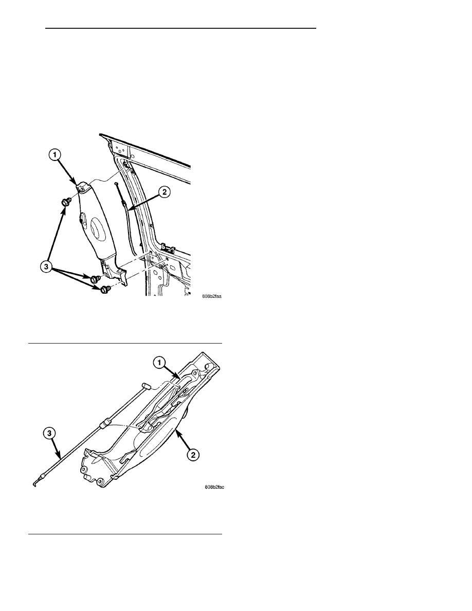
(6) Disengage cable end from release handle mech-
anism.
(7) Remove push pin fastener attaching cable end
to release handle.
(8) Disengage cable casing end from release handle
(Fig. 22).
(9) Disengage cable end from latch handle.
(10) Remove handle from vehicle.
INSTALLATION
(1) Place inside latch handle in position on vehicle.
(2) Engage cable end into latch handle.
(3) Engage cable casing end into release handle.
(4) Install push pin fastener to hold cable into
release handle.
(5) Engage cable end into release handle mecha-
nism.
(6) Engage clip to hold cable end into release han-
dle mechanism.
(7) Place latch handle in position on sliding door.
(8) Install screw to hold top of inside release han-
dle to sliding door.
(9) Install screws to hold bottom of inside latch
handle to sliding door.
(10) Verify sliding door operation. Adjust as neces-
sary. (Refer to 23 - BODY/DOORS - SLIDING/SLID-
ING DOOR - ADJUSTMENTS)
(11) Install sliding door trim panel. (Refer to 23 -
BODY/DOORS - SLIDING/TRIM PANEL - INSTAL-
LATION)
BELLCRANK
REMOVAL
(1) Remove stop bumper (Refer to 23 - BODY/
DOORS - SLIDING/STOP BUMPER - REMOVAL).
(2) Remove sliding door trim panel. (Refer to 23 -
BODY/DOORS
-
SLIDING/TRIM
PANEL
-
REMOVAL)
(3) Peel watershield away from adhesive around
perimeter of inner door panel as necessary to gain
access to latch bellcrank.
(4) Disengage lock link (Fig. 23).
(5) Disengage link and sleeve
(6) Remove bellcrank by rotating bellcrank to
release it from door.
(7) Remove bellcrank from vehicle.
INSTALLATION
(1) Position bellcrank on vehicle.
(2) Rotate bellcrank into position.
(3) Place lock link into position and engage clip
(Fig. 23).
(4) Place link and sleeve into position and engage
clip.
(5) Place the watershield into position and press
securely to adhesive making sure to properly route
wiring and linkages.
(6) Install sliding door trim panel (Refer to 23 -
BODY/DOORS - SLIDING/TRIM PANEL - INSTAL-
LATION).
(7) Install stop bumper (Refer to 23 - BODY/
DOORS - SLIDING/STOP BUMPER - INSTALLA-
TION).
Fig. 21 SLIDING DOOR INSIDE HANDLE
1 - INSIDE ASSIST HANDLE
2 - INSIDE RELEASE HANDLE CABLE
3 - ATTACHING SCREWS
Fig. 22 RELEASE HANDLE CABLE
1 - ASSIST HANDLE MECHANISM
2 - SLIDING DOOR INSIDE ASSIST HANDLE
3 - RELEASE HANDLE CABLE
RS
DOORS - SLIDING
23 - 39
INSIDE LATCH HANDLE (Continued)