Chrysler RG Voyager. Manual - part 1113


  Index      Chrysler     Chrysler RG Voyager - service repair manual 2005 year


Search            


Content   ..  1111  1112  1113  1114   ..


Chrysler RG Voyager. Manual - part 1113


INSTALLATION

NOTE: For power sliding door procedures refer to
POWER SLIDING DOOR SYSTEM in the ELECTRI-
CAL section.

(1) Position latch/lock locking lever in unlocked

position.

(2) If equipped, engage wire connector into power

door lock motor (Fig. 4).

(3) Place latch/lock in position on door (Fig. 5).

CAUTION: REPLACE BOLTS IF INSTALLING NEW
LATCH.

(4) Insert bolt into slots in sliding door inner

panel.

(5) Tighten bolts attaching latch/lock assembly to

sliding door.

(6) Engage inside cable into latch/lock assembly.
(7) Install inside door handle assembly (Refer to

23 - BODY/DOORS - SLIDING/INSIDE LATCH
HANDLE - INSTALLATION).

(8) Install foam block.
(9) Engage external cable to latch/lock assembly.
(10) Engage link rod to bellcrank.
(11) Engage hold open latch cable from lower

hinge.

(12) Engage clip to hold bellcrank link to latch/lock

control.

(13) Verify sliding door operation.

(14) Install latch/lock cover.
(15) Insure

that

enough

adhesive

remains

to

securely retain the watershield. Replace as necessary.

(16) Place the watershield into position and press

securely to adhesive making sure to properly route
wiring and linkages.

(17) Install sliding door stop bumper. (Refer to 23 -

BODY/DOORS

-

SLIDING/STOP

BUMPER

-

INSTALLATION)

(18) Install sliding door trim panel. (Refer to 23 -

BODY/DOORS - SLIDING/TRIM PANEL - INSTAL-
LATION)

INSIDE HANDLE ACTUATOR

REMOVAL

(1) Remove latch/lock assembly. (Refer to 23 -

BODY/DOORS - SLIDING/LATCH/LOCK CONTROL
- REMOVAL).

(2) Remove lock actuator three attaching screws

(Fig. 6).

(3) Remove lock actuator.

INSTALLATION

(1) Place lock actuator into position on latch/lock

assembly.

(2) Insall attaching screws (Fig. 6).
(3) Install latch/lock assembly. (Refer to 23 -

BODY/DOORS - SLIDING/LATCH / LOCK CON-
TROL - INSTALLATION).

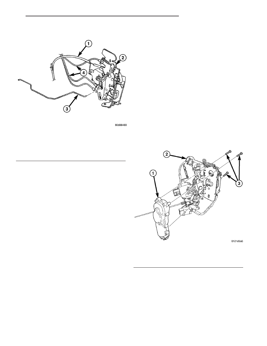
Fig. 5 REMOVING SLIDING DOOR LATCH/LOCK

ASSEMBLY

1 - WIRE HARNESS
2 - LATCH/LOCK ASSEMBLY
3 - BELLCRANK LINK ROD
4 - LINK AND SLEEVE ASSEMBLY

Fig. 6 LOCK ACTUATOR

1 - INSIDE HANDLE ACTUATOR
2 - LATCH/LOCK ASSEMBLY
3 - THREE ATTACHING SCREWS

RS

DOORS - SLIDING

23 - 31

LATCH / LOCK ASSEMBLY (Continued)

CENTER STRIKER

REMOVAL

(1) Remove sliding door trim panel. (Refer to 23 -

BODY/DOORS

-

SLIDING/TRIM

PANEL

-

REMOVAL)

(2) Remove bolts attaching stop bumper. Remove

stop bumper from door.

(3) Remove screws attaching center striker assem-

bly to door end frame (Fig. 7).

(4) Remove center striker assembly from door

through access hole.

INSTALLATION

(1) Place center striker in position on door through

access hole (Fig. 7).

(2) Install screws to attach center striker to door

end frame.

(3) Install bolts attaching stop bumper.
(4) Install sliding door trim panel (Refer to 23 -

BODY/DOORS - SLIDING/TRIM PANEL - INSTAL-
LATION).

LOWER HINGE

REMOVAL

NOTE: For power sliding door procedures refer to
POWER SLIDING DOOR SYSTEM in the ELECTRI-
CAL section.

(1) Open sliding door.
(2) Mark outline of roller arm on sliding door to

aid installation (Fig. 8).

(3) Remove sliding door sill plate. (Refer to 23 -

BODY/INTERIOR/SLIDING DOOR SILL PLATE -
REMOVAL)

(4) Remove screws attaching open latch to lower

roller arm.

(5) Remove open latch from lower arm.
(6) Support sliding door on a suitable lifting device

with a padded upper surface. The door must be
moveable with lifting device in place.

(7) Remove hold open latch striker.
(8) Remove bolts attaching lower roller arm to

sliding door.

(9) Remove roller arm from sliding door.
(10) Disengage roller arm from lower channel.
(11) Remove roller arm from vehicle.

INSTALLATION

NOTE: For power sliding door procedures refer to
POWER SLIDING DOOR SYSTEM in the ELECTRI-
CAL section.

(1) Place roller arm into position (Fig. 8).
(2) Engage roller arm to lower channel.
(3) Install roller arm to sliding door.
(4) Install bolts attaching lower roller arm to slid-

ing door.

(5) Install hold open latch striker.
(6) Install screws attaching open latch to lower

roller arm.

(7) Install sliding door sill plate. (Refer to 23 -

BODY/INTERIOR/SLIDING DOOR SILL PLATE -
INSTALLATION)

(8) Check sliding door for proper operation.

Fig. 7 SLIDING DOOR CENTER STRIKER

ASSEMBLY

1 - STRIKER BOLT ASSEMBLY
2 - SLIDING DOOR

Fig. 8 SLIDING DOOR LOWER ROLLER ARM

1 - POWER LOWER ROLLER ARM
2 - MANUAL LOWER ROLLER ARM

23 - 32

DOORS - SLIDING

RS

REAR LATCH STRIKER

REMOVAL

(1) Open sliding door.
(2) Mark outline of striker on C-pillar door jamb

face to aid installation.

(3) Remove screws attaching striker to C-pillar

(Fig. 9).

(4) Remove striker from vehicle.

INSTALLATION

(1) Place striker in position on vehicle.
(2) Align striker to outline marks on C-pillar.
(3) Install screws attaching striker to C-pillar.

Tighten screws to 28 N·m (21 ft. lbs.) torque.

(4) Verify sliding door alignment and operation.

SLIDING DOOR

REMOVAL

NOTE: For power sliding door procedures refer to
POWER SLIDING DOOR SYSTEM in the ELECTRI-
CAL section.

(1) Apply masking tape to outside surface of quar-

ter panel below the center roller channel, rearward of
the door opening.

(2) Release sliding door latch and open door.
(3) Apply masking tape to door jamb area, rear-

ward of the upper roller channel.

(4) Remove screw attaching upper stop bumper to

upper roller arm (Fig. 10).

(5) Remove upper stop from upper roller arm.
(6) Remove center stop from sliding door. (Refer to

23 - BODY/DOORS - SLIDING/STOP BUMPER -
REMOVAL)

(7) Remove sliding door sill plate. (Refer to 23 -

BODY/INTERIOR/SLIDING DOOR SILL PLATE -
REMOVAL)

(8) Remove hold open latch striker (Refer to 23 -

BODY/DOORS - SLIDING/HOLD OPEN LATCH
STRIKER - REMOVAL).

(9) Open quarter glass.
(10) Remove center roller channel end cover (Fig.

11).

(11) Support sliding door on a suitable lifting

device with a padded upper surface. The door must
be moveable with lifting device in place.

CAUTION: Do not allow the center hinge roller to
contact the quarter glass. Glass can break.

(12) Slide door rearward until the upper sliding

door hinge roller disengages from the upper channel
(Fig. 12).

(13) Continue moving the door rearward until the

lower rollers exit the lower track.

(14) Continue moving door rearward till center

hinge roller exits the channel (Fig. 13)

(15) Remove sliding door from vehicle.

Fig. 9 SLIDING DOOR LATCH STRIKER

1 - LATCH STRIKER
2 - SLIDING DOOR

Fig. 10 SLIDING DOOR UPPER STOP

1 - UPPER STOP PLATE
2 - SLIDING DOOR
3 - UPPER SLIDING DOOR HINGE

RS

DOORS - SLIDING

23 - 33

INSTALLATION

NOTE: For power sliding door procedures refer to
POWER SLIDING DOOR SYSTEM in the ELECTRI-
CAL section.

(1) Place sliding door in position on lifting device.
(2) Engage center hinge roller into channel and

move door forward (Fig. 13).

(3) Position door rearward of the sliding door open-

ing.

CAUTION: Do not allow the center hinge roller to
contact the quarter glass. Glass can break.

(4) Engage the center hinge roller into the channel

(Fig. 13).

(5) Roll door forward until lower roller engage into

rear of the track.

(6) Engage the upper sliding door hinge into the

upper channels (Fig. 12).

(7) Install hold open latch striker (Refer to 23 -

BODY/DOORS - SLIDING/HOLD OPEN LATCH
STRIKER - INSTALLATION).

(8) Install sliding door sill plate.
(9) Install center roller channel end cover (Fig. 11).
(10) Install center stop on sliding door. (Refer to 23

-

BODY/DOORS

-

SLIDING/STOP

BUMPER

-

INSTALLATION)

(11) Place upper roller stop bumper in position on

upper roller arm.

(12) Install screw attaching upper roller arm stop

bumper to upper roller arm (Fig. 10).

(13) Remove masking tape from body surfaces.
(14) Verify door operation and fit. Adjust as neces-

sary. (Refer to 23 - BODY/DOORS - SLIDING/SLID-
ING DOOR - ADJUSTMENTS)

ADJUSTMENTS

SLIDING DOOR ADJUSTMENTS

NOTE: For power sliding door procedures refer to
POWER SLIDING DOOR SYSTEM in the ELECTRI-
CAL section.

PRELIMINARY CHECKS

(1) Close the sliding door, visually checking C-pil-

lar striker alignment entry into latch. Striker at this

Fig. 11 CENTER CHANNEL END COVER

1 - CENTER CHANNEL
2 - CENTER CHANNEL END COVER
3 - PLASTIC NUT

Fig. 12 SLIDING DOOR UPPER ROLLER

1 - SLIDING DOOR
2 - UPPER HINGE
3 - UPPER CHANNEL

Fig. 13 SLIDING DOOR CENTER ROLLER

1 - SLIDING DOOR
2 - QUARTER GLASS
3 - CENTER HINGE ROLLERS
4 - CENTER HINGE

23 - 34

DOORS - SLIDING

RS

SLIDING DOOR (Continued)


Content   ..  1111  1112  1113  1114   ..