Chrysler PT Cruiser. Manual - part 975
NOTE: For circuit descriptions and diagrams, refer
to the appropriate wiring information. The wiring
information includes wiring diagrams, proper wire
and connector repair procedures, further details on
wire harness routing and retention, as well as pin-
out and location views for the various wire harness
connectors, splices and grounds.
(1) Disconnect and isolate the negative battery
cable.
(2) Disconnect the wire harness connector from the
blower motor resistor (Refer to 24 - HEATING & AIR
CONDITIONING/CONTROLS/BLOWER
MOTOR
RESISTOR - REMOVAL).
(3) Using
an
ohmmeter,
check
for
continuity
between all of the blower motor resistor terminals. In
each case there should be continuity. If OK, repair
the wire harness circuits between the blower motor
switch and the blower motor resistor or blower motor
as required. If not OK, replace the faulty blower
motor resistor.
REMOVAL
WARNING: The blower motor resistor may get very
hot during normal operation. If the blower motor
was turned on prior to servicing the blower motor
resistor, wait five minutes to allow the blower motor
resistors to cool before performing diagnosis or
service. Failure to take this precaution can result in
possible personal injury.
CAUTION: Do not operate the blower motor with the
blower motor resistor removed from the circuit.
Failure to take this precaution can result in vehicle
damage.
(1) Disconnect and isolate the negative battery
cable.
(2) Remove the windshield wipers (Refer to 8 -
ELECTRICAL/WIPERS/WASHERS/WIPER ARMS -
REMOVAL).
(3) Remove the cowl top screen (Refer to 23 -
BODY/EXTERIOR/COWL
GRILLE
SCREEN
-
REMOVAL).
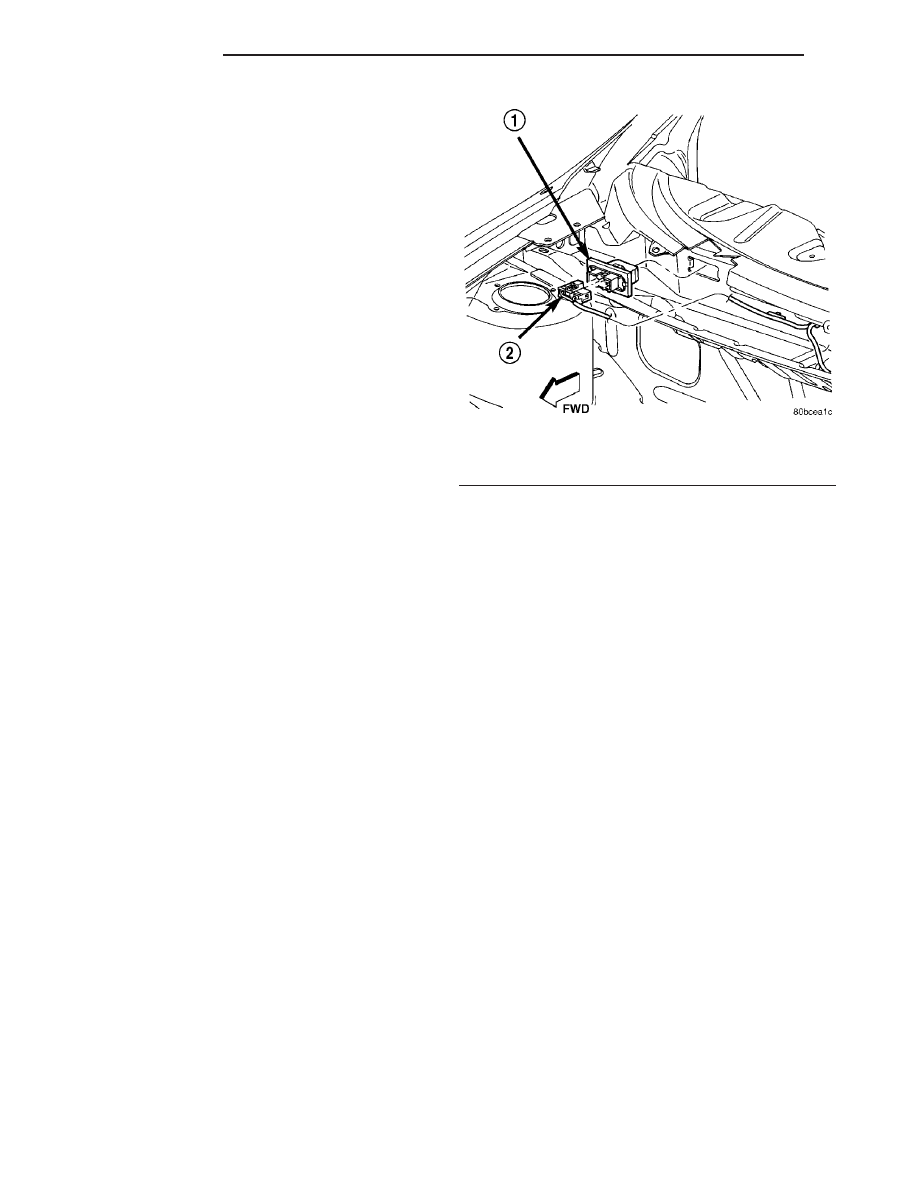
(4) Disconnect the wire harness connector from the
blower motor resistor (Fig. 16).
(5) Disengage the retaining clip and remove the
blower motor resistor from the engine compartment.
INSTALLATION
(1) Position the blower motor resistor into the
engine compartment.
(2) Install the blower motor resistor into the cowl
and engage the retaining clip.
(3) Connect the wire harness connector to the
blower motor resistor.
(4) Install the cowl top screen (Refer to 23 -
BODY/EXTERIOR/COWL
GRILLE
SCREEN
-
INSTALLATION).
(5) Install the windshield wipers (Refer to 8 -
ELECTRICAL/WIPERS/WASHERS/WIPER ARMS -
INSTALLATION).
(6) Reconnect the negative battery cable.
MODE DOOR CABLE
REMOVAL
NOTE: The mode control cable can be removed and
installed without having to remove the instrument
panel from the vehicle.
(1) Disconnect and isolate the negative battery
cable.
(2) Remove instrument panel center bezel (Refer to
23 - BODY/INSTRUMENT PANEL/INSTRUMENT
PANEL CENTER BEZEL - REMOVAL).
(3) Remove the center air duct (Refer to 24 -
HEATING & AIR CONDITIONING/DISTRIBUTION/
AIR OUTLETS - REMOVAL).
(4) Remove the A/C-heater control (Refer to 24 -
HEATING & AIR CONDITIONING/CONTROLS/A/C
HEATER CONTROL - REMOVAL).
(5) Reach through the center air duct opening in
the instrument panel to access and remove the screw
that secures the mode control cable housing to the
top of the HVAC housing (Fig. 17).
Fig. 16 Blower Motor Resistor - Typical
1 - BLOWER MOTOR RESISTOR
2 - ELECTRICAL CONNECTOR
24 - 22
CONTROLS
PT
BLOWER MOTOR RESISTOR (Continued)