Chrysler PT Cruiser. Manual - part 922


  Index      Chrysler     Chrysler PT Cruiser - service repair manual 2005 year


Search            


Content   ..  920  921  922  923   ..


Chrysler PT Cruiser. Manual - part 922


FRONT SEAT BACK - WITH
FRONT SEAT BACK PANEL

REMOVAL

WARNING: BEFORE SERVICING THE SEAT BACK
THE AIRBAG SYSTEM MUST BE DISARMED. FAIL-
URE TO DO SO MAY RESULT IN ACCIDENTAL
DEPLOYMENT OF THE AIRBAG AND POSSIBLE
PERSONAL INJURY. REFER TO RESTRAINT SYS-
TEMS FOR SERVICE PROCEDURES.

CAUTION: Do not reuse the recliner assembly
attaching bolts.

(1) Remove seat from vehicle (Refer to 23 - BODY/

SEATS/SEAT - REMOVAL).

(2) Remove the inner seat cushion shield (Fig. 3).

(3) Remove the seat back recliner handle/fold flat

handle and front seat cushion shield. (Fig. 4) Discon-
nect wire connectors, if equipped (Fig. 5).

Fig. 3 SEAT SIDE SHIELD - INBOARD

1 - FRONT INNER SEAT BELT ATTACHING SCREW
2 - SHIELD ATTACHING SCREWS

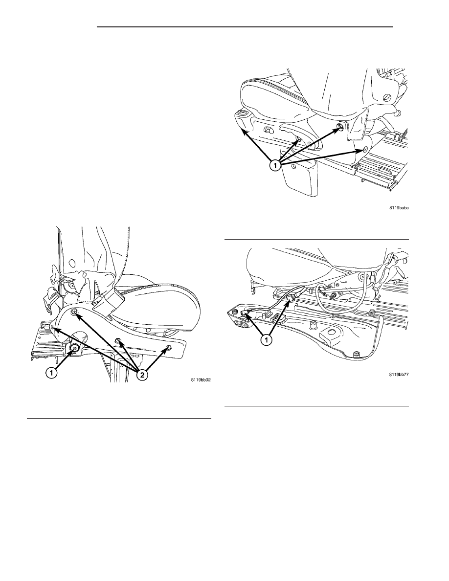
Fig. 4 SEAT SHIELD - OUTBOARD

1 - ATTACHING SCREWS

Fig. 5 SEAT SIDE SHIELD WIRE CONNECTORS

1 - WIRE CONNECTORS

23 - 146

SEATS

PT

(4) Remove seat armrest plug (Fig. 6).

(5) Remove seat armrest and lumbar handle if

equipped (Fig. 7).

(6) Remove front seat back panel (Fig. 8).

(7) Disengage J-straps (Fig. 9)

Fig. 6 ARMREST PLUG

1 - ARMREST
2 - PLUG

Fig. 7 ARMREST SCREW

1 - ARMREST
2 - ARMREST SCREW
3 - LUMBAR HANDLE
4 - LUMBAR HANDLE SCREW

Fig. 8 FRONT SEAT BACK PANEL

1 - ATTACHING SCREWS
2 - FRONT SEAT BACK PANEL

Fig. 9 FRONT SEAT COVER J-STRAPS

1- J-STRAPS

PT

SEATS

23 - 147

FRONT SEAT BACK - WITH FRONT SEAT BACK PANEL (Continued)

(8) Disengage the lower seat cover J-straps (Fig.

10).

(9) Remove upper riser shield, if equipped.
(10) Move seat cover and cushion to access the

front seat back recliner.

(11) Remove two attaching lumbar actuator screws

from the inner seat back frame (Fig. 11).

(12) Move lumbar actuator free the front seat back

recliner (Fig. 12).

(13) Remove screws attaching recliner to seat back

cushion frame on both sides (Fig. 13).

Fig. 10 FRONT SEAT BACK LOWER J-STRAPS

1 - LOWER J-STRAPS

Fig. 11 LUMBAR BRACKET ATTACHING SCREWS

1 - LUMBAR BRACKET ATTACHING SCREWS

Fig. 12 LUMBAR MOUNTING BRACKET

1 - LUMBAR MOUNTING BRACKET

Fig. 13 FRONT SEAT BACK ATTACHING SCREWS

1 - FRONT SEAT BACK
2 - ATTACHING SCREWS

23 - 148

SEATS

PT

FRONT SEAT BACK - WITH FRONT SEAT BACK PANEL (Continued)

(14) Vehicle with Seat Airbag and/or Heated Seat

System, remove front seat cushion frame. Remove
two front side screws and two rear screws (Fig. 14)
and (Fig. 15).

(15) Disconnect any electrical connectors and wire

ties from the seat back that are connected under the
seat cushion, if equipped.

(16) Remove seat back frame from seat assembly.

INSTALLATION

WARNING: BEFORE SERVICING THE SEAT BACK
THE AIRBAG SYSTEM MUST BE DISARMED. FAIL-
URE TO DO SO MAY RESULT IN ACCIDENTAL
DEPLOYMENT OF THE AIRBAG AND POSSIBLE
PERSONAL INJURY. REFER TO RESTRAINT SYS-
TEMS FOR SERVICE PROCEDURES.

CAUTION: Do not reuse the recliner assembly
attaching bolts.

(1) Position seat back on seat back frame.
(2) Start the screws attaching recliner to seat back

cushion frame on both sides (Fig. 16).

(3) Vehicle with Seat Airbag and/or Heated Seat

System, connect electrical connector(s) under the seat
cushion. Using wire ties secure the wire harness to
the seat cushion frame.

(4) Install two front side screws and two rear

screws attaching seat cushion (Fig. 17) and (Fig. 18).

(5) Tighten screws attaching recliner to seat cush-

ion frame. Tighten screws to 12 N·m (9 ft. lbs.)
torque.

Fig. 14 FRONT SIDE ATTACHING SCREW FRONT

CUSHION

1 - FRONT SIDE ATTACHING SCREW
2 - FRONT SEAT CUSHION

Fig. 15 REAR ATTACHING SCREW - FRONT SEAT

CUSHION

1 - REAR ATTACHING SCREW
2 - FRONT SEAT CUSHION

Fig. 16 FRONT SEAT BACK ATTACHING SCREWS

1 - FRONT SEAT BACK
2 - ATTACHING SCREWS

PT

SEATS

23 - 149

FRONT SEAT BACK - WITH FRONT SEAT BACK PANEL (Continued)


Content   ..  920  921  922  923   ..