Chrysler PT Cruiser. Manual - part 831


  Index      Chrysler     Chrysler PT Cruiser - service repair manual 2005 year


Search            


Content   ..  829  830  831  832   ..


Chrysler PT Cruiser. Manual - part 831


(4) Return the ignition key to the “LOCK” position

(Fig. 311).

(5) Connect the BTSI solenoid connector (Fig. 310).
(6) Install

steering

column

upper

and

lower

shrouds (Fig. 309).

(7) Install steering column lower cover (Fig. 308).
(8) Verify that shifter is in gated “PARK”.
(9) Install the cable core end to the plastic cam of

the shifter mechanism. Snap the shifter/ignition
interlock cable end fitting into the groove in the gear-
shift mechanism as shown in (Fig. 307).

(10) Adjust interlock cable/system as follows:

If interlock cable is being replaced, it will come with
an adjustment pin. Remove the pin from the cable
and allow the cable to “self-adjust”. Lock cable
adjustment by pressing down on the adjuster lock
until bottomed at the cable housing. If interlock cable
is being re-used, no pin will be provided. Pry up on
cable adjuster lock to release and allow cable to “self-
adjust”. Lock cable adjustment by pressing down on
the adjuster lock until bottomed at the cable housing.

(11) Connect battery negative cable and ver-

ify interlock system operation as follows:

ACTION

EXPECTED RESPONSE

1. Turn key to the

9

OFF

9

position.

1. Shifter CAN be shifted
out of park.

2. Turn key to the

9

ON/RUN

9

position.

2. Shifter CANNOT be
shifted out of park.

3. Turn key to the

9

ON/RUN

9

position and

depress the brake pedal.

3. Shifter CAN be shifted
out of park.

4. Leave shifter in any
gear and try to return key
to the

9

LOCK

9

or

9

ACC

9

position.

4. Key cannot be
returned to the

9

LOCK

9

or

9

ACC

9

position.

5. Return shifter to

9

PARK

9

and try to remove

the key.

5. Key can be removed
(after returning to

9

LOCK

9

position).

6. With the key removed,
try to shift out of

9

PARK

9

.

6. Shifter cannot be
shifted out of

9

PARK

9

.

NOTE: Any failure to meet these expected
responses requires system adjustment or repair.

(12) Install shifter bezel (Fig. 306).
(13) Install center console assembly (Fig. 305).
(14) Install gearshift knob and tighten set screw to

2 N·m (17 in. lbs.) torque (Fig. 304).

(15) Connect battery negative cable.

SHIFT INTERLOCK
MECHANISM

REMOVAL

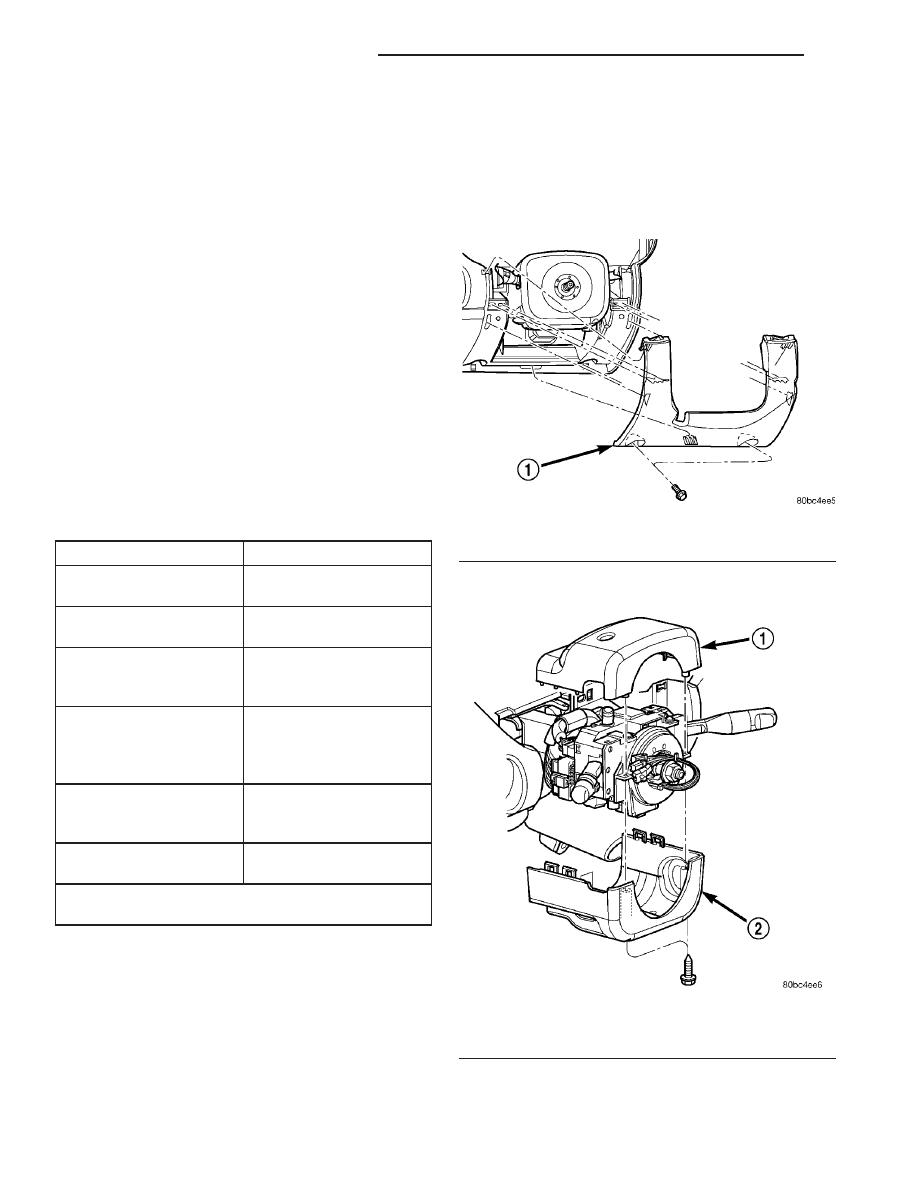
(1) Remove the steering column lower cover (Fig.

314).

(2) Remove the steering column upper and lower

shrouds (Fig. 315).

Fig. 314 Steering Column Lower Cover

1 - LOWER COVER

Fig. 315 Steering Column Shrouds

1 - UPPER SHROUD
2 - LOWER SHROUD

21 - 278

40TE AUTOMATIC TRANSAXLE

PT

SHIFT INTERLOCK CABLE (Continued)

(3) Turn the ignition key to the “OFF” or “ON/

RUN” position (Fig. 316).

(4) Grasp the interlock cable and connector firmly.

Remove the interlock cable (Fig. 317).

(5) Remove the two interlock mechanism-to-steer-

ing column attaching screws (Fig. 318). Remove the
interlock housing.

INSTALLATION

(1) Position the interlock housing at steering col-

umn. Install the two interlock mechanism-to-steering
column attaching screws. Torque screws to 3 N·m (21
in. lbs.).

(2) Snap the interlock cable into the housing.
(3) Install

steering

column

upper

and

lower

shrouds (Fig. 315).

(4) Install steering column lower cover (Fig. 314).

SHIFT INTERLOCK SYSTEM

DESCRIPTION

The Brake Transmission Shifter/Ignition Interlock

(BTSI) is a cable and solenoid operated system that
prevents the transmission gear shifter from being
moved out of PARK without a driver in place.

Refer to the following chart that expected shifter

response, depending on ignition key/switch (Fig. 319)
and brake pedal positions.

DIAGNOSIS AND TESTING - BRAKE/
TRANSMISSION SHIFT INTERLOCK SYSTEM

The following chart describes the normal operation

of the Brake Transmission Shift Interlock (BTSI) sys-
tem. If the “expected response” differs from the vehi-

Fig. 316 Ignition Key/Switch Positions

1 - ACC
2 - LOCK
3 - OFF
4 - ON/RUN
5 - START

Fig. 317 Interlock Cable

1 - IGNITION LOCK CYLINDER
2 - INTERLOCK CABLE

Fig. 318 Interlock Mechanism

1 - MOUNTING SCREW
2 - INTERLOCK MECHANISM

Fig. 319 Ignition Key/Switch Positions

1 - ACC
2 - LOCK
3 - OFF
4 - ON/RUN
5 - START

PT

40TE AUTOMATIC TRANSAXLE

21 - 279

SHIFT INTERLOCK MECHANISM (Continued)

cle’s response, then system repair and/or adjustment
is necessary.

Refer to the following chart that expected shifter

response, depending on ignition key/switch (Fig. 320)
and brake pedal positions.

ACTION

EXPECTED RESPONSE

1. Turn key to the

9

OFF

9

position.

1. Shifter CAN be shifted
out of park.

2. Turn key to the

9

ON/RUN

9

position.

2. Shifter CANNOT be
shifted out of park.

3. Turn key to the

9

ON/RUN

9

position and

depress the brake pedal.

3. Shifter CAN be shifted
out of park.

4. Leave shifter in any
gear and try to return key
to the

9

LOCK

9

or

9

ACC

9

position.

4. Key cannot be
returned to the

9

LOCK

9

or

9

ACC

9

position.

5. Return shifter to

9

PARK

9

and try to remove

the key.

5. Key can be removed
(after returning to

9

LOCK

9

position).

6. With the key removed,
try to shift out of

9

PARK

9

.

6. Shifter cannot be
shifted out of

9

PARK

9

.

NOTE: Any failure to meet these expected
responses requires system adjustment or repair.

ADJUSTMENTS

BRAKE/TRANSMISSION SHIFT INTERLOCK
SYSTEM

VERIFICATION

The following chart describes the normal operation

of the Brake Transmission Shift Interlock (BTSI) sys-

tem. If the “expected response” differs from the vehi-
cle’s response, then system repair and/or adjustment
is necessary.

ACTION

EXPECTED RESPONSE

1. Turn key to the

9

OFF

9

position.

1. Shifter CAN be shifted
out of park.

2. Turn key to the

9

ON/RUN

9

position.

2. Shifter CANNOT be
shifted out of park.

3. Turn key to the

9

ON/RUN

9

position and

depress the brake pedal.

3. Shifter CAN be shifted
out of park.

4. Leave shifter in any
gear and try to return key
to the

9

LOCK

9

or

9

ACC

9

position.

4. Key cannot be
returned to the

9

LOCK

9

or

9

ACC

9

position.

5. Return shifter to

9

PARK

9

and try to remove

the key.

5. Key can be removed
(after returning to

9

LOCK

9

position).

6. With the key removed,
try to shift out of

9

PARK

9

.

6. Shifter cannot be
shifted out of

9

PARK

9

.

NOTE: Any failure to meet these expected
responses requires system adjustment or repair.

ADJUSTMENT

(1) Loosen set screw and remove knob from shifter

handle (Fig. 321).

Fig. 320 Ignition Key/Switch Positions

1 - ACC
2 - LOCK
3 - OFF
4 - ON/RUN
5 - START

Fig. 321 Gearshift Knob

1 - SHIFTER KNOB
2 - SET SCREW

21 - 280

40TE AUTOMATIC TRANSAXLE

PT

SHIFT INTERLOCK SYSTEM (Continued)

(2) Remove the center console assembly as shown

in (Fig. 322).

(3) Remove shifter bezel (Fig. 323).

(4) Adjust interlock cable/system as follows:

Pry up on cable adjuster lock to release and allow
cable to “self-adjust”. Lock cable adjustment by press-
ing down on the adjuster lock until bottomed at the
cable housing.

(5) Verify correct system operation. Refer to verifi-

cation procedure.

(6) Install shifter bezel (Fig. 323).
(7) Install center console assembly (Fig. 322).

(8) Install gearshift knob and tighten set screw to

2 N·m (17 in. lbs.) torque (Fig. 321).

SOLENOID/PRESSURE
SWITCH ASSY

DESCRIPTION

The Solenoid/Pressure Switch Assembly (Fig. 324)

is external to the transaxle and mounted to the
transaxle case. The assembly consists of four sole-
noids that control hydraulic pressure to the LR/CC,
2/4, OD, and UD friction elements. The reverse
clutch is controlled by line pressure from the manual
valve in the valve body. The solenoids are contained
within the Solenoid/Pressure Switch Assembly, and
can only be serviced by replacing the assembly.

The solenoid assembly also contains pressure

switches that monitor and send hydraulic circuit
information to the PCM/TCM. Likewise, the pressure
switches can only be service by replacing the assem-
bly.

OPERATION

SOLENOIDS

The solenoids receive electrical power from the

Transmission Control Relay through a single wire.
The PCM/TCM energizes or operates the solenoids
individually by grounding the return wire of the sole-
noid needed. When a solenoid is energized, the sole-
noid valve shifts, and a fluid passage is opened or

Fig. 322 Center Console Removal/Installation

1 - CENTER CONSOLE

Fig. 323 Shifter Bezel Removal/Installation

1 - BEZEL
2 - SCREW (4)

Fig. 324 Solenoid/Pressure Switch Assembly

1 - SOLENOID AND PRESSURE SWITCH ASSEMBLY

PT

40TE AUTOMATIC TRANSAXLE

21 - 281

SHIFT INTERLOCK SYSTEM (Continued)


Content   ..  829  830  831  832   ..