Chrysler PT Cruiser. Manual - part 783


  Index      Chrysler     Chrysler PT Cruiser - service repair manual 2005 year


Search            


Content   ..  781  782  783  784   ..


Chrysler PT Cruiser. Manual - part 783


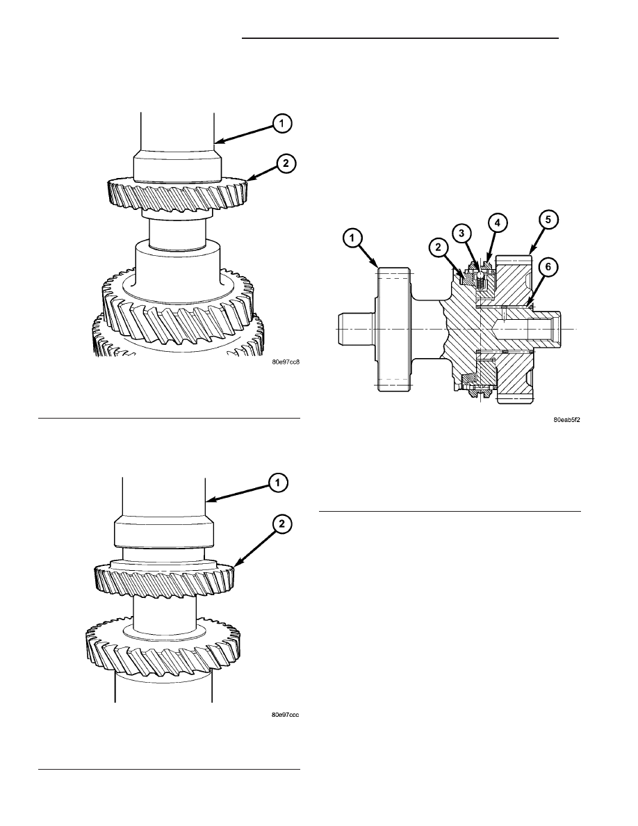
(17) Using Tool 6448A, press fourth gear (collar

down) until it bottoms (Fig. 223).

(18) Using Tool 6448A, press fifth gear (collar up)

until it bottoms (Fig. 224).

REVERSE SHAFT

DESCRIPTION

The reverse shaft assembly (Fig. 225) consists of a

fixed gear shaft, the reverse synchronizer, and a free
gear wheel that rotates about two (2) needle bear-
ings. The assembly is supported on one end (clutch
bellhousing) by a sealed roller bearing, and a needle
bearing at the other end (geartrain housing).

Fig. 223 Fourth Gear Installation

1 - TOOL 6448A
2 - FOURTH GEAR (COLLAR DOWN)

Fig. 224 Fifth Gear Installation

1 - TOOL 6448A
2 - FIFTH GEAR (COLLAR UP)

Fig. 225 Reverse Shaft Section View

1 - SHAFT W/GEAR
2 - BLOCKER RING
3 - STRUT ASSEMBLY
4 - SLEEVE
5 - GEAR (REVERSE)
6 - NEEDLE BEARING (2)

21 - 86

G288 MANUAL TRANSAXLE

PT

OUTPUT SHAFT (Continued)

DISASSEMBLY

(1) Remove roller bearing retaining screw (Fig.

226). Use glove or install shaft assembly to soft-jaw-
wed vice.

(2) Set reverse shaft assembly on arbor press bed

supported by bearing splitter P-334. Using Tool 8923,
remove reverse gear, thrust washer, and bearing
from reverse shaft assembly (Fig. 227) (Fig. 228).

Fig. 226 Remove Bearing Retaining Screw

1 - GLOVE
2 - SCREW
3 - BEARING

Fig. 227 Remove Bearing and Reverse Gear

1 - PRESS RAM
2 - TOOL 8923
3 - BEARING
4 - GEAR/SYNCHRO
5 - BEARING SPLITTER

Fig. 228 Reverse Gear and Synchronizer

1 - REVERSE GEAR
2 - SYNCHRONIZER
3 - NEEDLE BEARINGS
4 - BLOCKER RING

PT

G288 MANUAL TRANSAXLE

21 - 87

REVERSE SHAFT (Continued)

(3) Remove synchronizer sleeve and strut assem-

blies from gear/synchronizer hub assembly (Fig. 229).

(4) Remove blocker ring from reverse shaft assem-

bly (Fig. 230).

(5) Remove needle bearings from reverse shaft

(Fig. 231).

ASSEMBLY

(1) Install synchronizer sleeve to gear/hub assem-

bly with GROOVE UP as shown in (Fig. 232).

Fig. 229 Reverse Synchronizer Sleeve

1 - SYNCHRO SLEEVE
2 - GROOVE UP
3 - GEAR/SYNCHRO HUB

Fig. 230 Reverse Blocker Ring

1 - BLOCKER RING
2 - SHAFT ASSY.

Fig. 231 Reverse Gear Needle Bearings

1 - NEEDLE BEARING (2)

Fig. 232 Reverse Synchronizer Sleeve

1 - SYNCHRO SLEEVE
2 - GROOVE UP
3 - GEAR/SYNCHRO HUB

21 - 88

G288 MANUAL TRANSAXLE

PT

REVERSE SHAFT (Continued)

(2) Install three (3) synchronizer strut assemblies

(Fig. 233).

(3) Install needle bearings to reverse shaft (Fig.

234).

(4) Install reverse blocker ring to shaft assembly

(Fig. 235).

(5) Install gear/synchronizer assembly to shaft

(Fig. 236). Verify that blocker ring is seated into syn-
chronizer hub for proper assembly.

Fig. 233 Synchronizer Strut Assembly

1 - STRUT (3)

Fig. 234 Reverse Gear Needle Bearings

1 - NEEDLE BEARING (2)

Fig. 235 Reverse Blocker Ring

1 - BLOCKER RING
2 - SHAFT ASSY.

Fig. 236 Reverse Gear and Synchronizer

1 - REVERSE GEAR
2 - SYNCHRONIZER
3 - NEEDLE BEARINGS
4 - BLOCKER RING

PT

G288 MANUAL TRANSAXLE

21 - 89

REVERSE SHAFT (Continued)


Content   ..  781  782  783  784   ..