Chrysler PT Cruiser. Manual - part 765


  Index      Chrysler     Chrysler PT Cruiser - service repair manual 2005 year


Search            


Content   ..  763  764  765  766   ..


Chrysler PT Cruiser. Manual - part 765


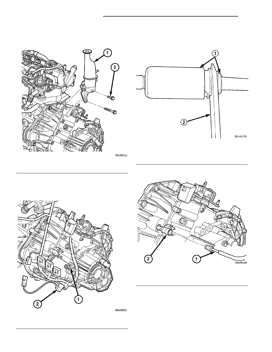
(6) Remove power steering reservoir mounting

bolts (Fig. 16).

(7) Disconnect back-up lamp switch connector (Fig.

17).

(8) Disconnect vehicle speed sensor connector (Fig.

17).

(9) Disconnect clutch master cylinder hydraulic

tube from clutch slave cylinder using Tool 6638A
(Fig. 18) (Fig. 19).

(10) Remove transaxle upper bellhousing-to-block

bolts.

(11) Raise vehicle on hoist.
(12) Remove transaxle drain plug and drain into

suitable container (Fig. 20).

(13) Remove halfshafts (Fig. 21).

Fig. 16 Power Steering Reservoir

1 - RESERVOIR
2 - BOLT

Fig. 17 VSS and Back-Up Lamp Switches

1 - BACK-UP LAMP SWITCH
2 - VEHICLE SPEED SENSOR (VSS)

Fig. 18 Disconnect Clutch Hydraulic Quick Connect

using Tool 6638A

1 - QUICK CONNECT FITTING
2 - TOOL 6638A

Fig. 19 Clutch Slave Cylinder Hydraulic Connection

1 - MASTER CYLINDER TUBE
2 - SLAVE CYLINDER

21 - 14

G288 MANUAL TRANSAXLE

PT

G288 MANUAL TRANSAXLE (Continued)

(14) Remove three (3) intermediate shaft bearing-

to-retainer bolts. Remove intermediate shaft/bearing
assembly (Fig. 21).

(15) Remove two (2) intercooler connector pipe-to-

engine oil pan bolts (Fig. 22) and position aside to
access and remove oil pan-to-bellhousing bolt.

(16) Position screw jack and wood block to engine

oil pan.

(17) Obtain access to engine compartment. Remove

two (2) transaxle upper mount-to-bracket bolts (Fig.
23).

Fig. 20 Transaxle Fluid Drain and Fill Plugs

1 - FILL PLUG
2 - DRAIN PLUG
3 - RIGHT AXLE SEAL

Fig. 21 Halfshaft and Intermediate Shaft

1 - HALFSHAFT (LH)
2 - TRANSAXLE
3 - INTERMEDIATE SHAFT

4 - BOLT (3)
5 - HALFSHAFT (RH)

PT

G288 MANUAL TRANSAXLE

21 - 15

G288 MANUAL TRANSAXLE (Continued)

(18) Lower engine/transaxle assembly on screw

jack.

(19) Remove transaxle upper mount bracket (Fig.

24).

(20) Position

transmission

jack

to

transaxle.

Secure transaxle to jack.

(21) Remove starter lower bolt with ground cable

(Fig. 25).

Fig. 22 Intercooler Inlet Hose Fasteners

1 - INTERCOOLER INLET HOSE
2 - SCREW (2)
3 - STRUCTURAL COLLAR

Fig. 23 Upper Mount-to-Bracket

1 - BOLT (2)
2 - MOUNT
3 - BRACKET

Fig. 24 Transaxle Upper Mount Bracket

1 - TRANSAXLE
2 - BRACKET
3 - BOLT

Fig. 25 Starter Bolt and Ground Cable

1 - GROUND CABLE
2 - BOLT
3 - STARTER MOTOR

21 - 16

G288 MANUAL TRANSAXLE

PT

G288 MANUAL TRANSAXLE (Continued)

(22) Remove remaining bellhousing-to-block bolts.
(23) Lower transaxle assembly from engine/vehi-

cle.

REMOVAL—2.4L TURBO

(1) Disconnect battery negative cable.
(2) Remove air cleaner assembly (Fig. 26).

(3) Remove Power Distribution Center (PDC) from

bracket. Remove Air Cleaner/PDC mounting bracket
(Fig. 27).

(4) Disconnect gearshift cables from shift mecha-

nism and bracket (Fig. 28). Position cables out of
way.

(5) Remove gearshift cable bracket (Fig. 28).
(6) Disconnect back-up lamp switch connector (Fig.

29).

(7) Disconnect vehicle speed sensor connector (Fig.

29).

(8) Disconnect clutch master cylinder hydraulic

tube from clutch slave cylinder using Tool 6638A
(Fig. 30) (Fig. 31).

Fig. 26 Air Cleaner Assembly—Typical

1 - DUCT
2 - MASS AIR FLOW SENSOR
3 - AIR CLEANER ASSEMBLY
4 - BRACKET

Fig. 27 Air Cleaner/PDC Bracket

1 - BRACKET
2 - BOLT (4)

Fig. 28 Gear Shift Cables and Bracket at Transaxle

1 - TRANSAXLE
2 - GEAR SHIFT CABLE BRACKET
3 - BOLT (3)
4 - CABLE ASSEMBLY
5 - RETAINER (2)

PT

G288 MANUAL TRANSAXLE

21 - 17

G288 MANUAL TRANSAXLE (Continued)


Content   ..  763  764  765  766   ..