Chrysler PT Cruiser. Manual - part 726


  Index      Chrysler     Chrysler PT Cruiser - service repair manual 2005 year


Search            


Content   ..  724  725  726  727   ..


Chrysler PT Cruiser. Manual - part 726


(11) Remove turbocharger lower heat shield (Fig.

27).

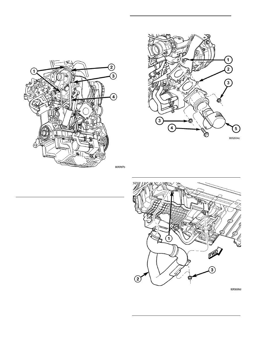
(12) Disconnect oil supply line at turbocharger

(Fig. 24).

(13) Remove coolant return line (Fig. 24).

(14) Disconnect vacuum hoses from turbocharger.
(15) Raise vehicle on hoist.
(16) Disconnect muffler ground strap. Remove

muffler (Refer to 11 - EXHAUST SYSTEM/MUF-
FLER - REMOVAL).

(17) Disconnect downstream oxygen sensor.
(18) Remove fasteners securing catalytic converter

to exhaust manifold (Fig. 25).

(19) Remove catalytic converter and intermediate

pipe as an assembly.

(20) Remove turbocharger to charge air cooler hose

assembly (Fig. 26).

(21) Remove turbocharger elbow support bracket

(Fig. 27).

(22) Remove turbocharger support bracket (Fig.

27).

(23) Remove oil return tube (Fig. 24).
(24) Remove turbocharger coolant supply line (Fig.

24).

(25) Remove turbocharger upper heat shield (Fig.

27).

(26) Remove turbocharger elbow (Fig. 27).

Fig. 24 Turbocharger Lines and Hoses

1 - OIL SUPPLY LINE
2 - COOLANT RETURN LINE
3 - COOLANT SUPPLY LINE
4 - OIL RETURN TUBE

Fig. 25 Converter to Exhaust Manifold Connection -

2.4L Turbo

1 - FLAG NUT
2 - GASKET
3 - NUT
4 - BOLT
5 - CATALYTIC CONVERTER

Fig. 26 Charge Air Cooler Hose

1 - CHARGE AIR COOLER
2 - HOSE - TURBOCHARGER TO CHARGE AIR COOLER
3 - NUT

11 - 18

EXHAUST SYSTEM AND TURBOCHARGER

PT

TURBOCHARGER (Continued)

(27) Remove lower exhaust manifold fasteners that

are accessible while vehicle is on hoist.

(28) Lower vehicle.
(29) Remove upper exhaust manifold fasteners.
(30) Remove

turbocharger/exhaust

manifold

assembly from above/between the engine and cowl
panel.

(31) Remove and discard exhaust manifold gasket.

INSPECTION - TYPICAL TURBOCHARGER

Visually inspect the turbocharger and exhaust

manifold gasket surfaces. Replace stripped or eroded
mounting studs.

(1) Visually inspect the turbocharger for cracks.

The following cracks are NOT acceptable:

• Cracks in the turbine and compressor housing

that go completely through.

• Cracks in the mounting flange that are longer

than 15 mm (0.6 in.).

• Cracks in the mounting flange that intersect

bolt through-holes.

• Two (2) Cracks in the mounting flange that are

closer than 6.4 mm (0.25 in.) together.

(2) Visually inspect the impeller and compressor

wheel fins for nicks, cracks, or chips.

(3) Visually inspect the turbocharger compressor

housing for an impeller rubbing condition (Fig. 28).
Replace the turbocharger if the condition exists.

(4) Measure the turbocharger axial end play:

(a) Install a dial indicator. Zero the indicator at

one end of travel.

(b) Move the impeller shaft fore and aft and

record the measurement. Allowable end play is
0.038 mm (0.0015 in.) MIN. and 0.089 mm (0.0035
in.) MAX. If the recorded measurement falls out-
side these parameters, replace the turbocharger
assembly.
(5) Measure the turbocharger bearing radial clear-

ance:

(a) Insert a narrow blade or wire style feeler

gauge between the compressor wheel and the hous-
ing.

(b) Gently push the compressor wheel toward

the housing and record the clearance.

(c) With the feeler gauge in the same location,

gently push the compressor wheel away from the
housing and again record the clearance.

(d) Subtract the smaller clearance from the

larger clearance. This is the radial bearing clear-
ance.

(e) Allowable radial bearing clearance is 0.326

mm (0.0128 in.) MIN. and 0.496 mm (0.0195 in.)
MAX. If the recorded measurement falls outside
these

specifications,

replace

the

turbocharger

assembly.

INSTALLATION - TURBOCHARGER

CAUTION: IF TURBOCHARGER IS REPLACED DUE
TO A BEARING FAILURE, REPLACEMENT OF THE
OIL PRESSURE FEED LINE IS REQUIRED. OIL
RETURN TUBE SHOULD BE CLEANED ALSO.

Fig. 27 Turbocharger Brackets and Heat Shields

1 - UPPER/LOWER HEAT SHIELDS
2 - TURBOCHARGER SUPPORT BRACKET
3 - ELBOW
4 - ELBOW SUPPORT BRACKET

Fig. 28 Inspect Compressor Housing for Impeller

Rubbing Condition

PT

EXHAUST SYSTEM AND TURBOCHARGER

11 - 19

TURBOCHARGER (Continued)

NOTE: The turbocharger and exhaust manifold are
serviced as an assembly. Do Not attempt to remove
the

turbocharger

from

the

exhaust

manifold.

Exhaust leaks will result. It is recommended that
the turbocharger elbow be replaced along with the
turbocharger/exhaust manifold assembly.

(1) Clean gasket sealing surfaces. Replace exhaust

manifold gasket. DO NOT APPLY SEALER TO
GASKET.

NOTE: Stainless steel layer of exhaust manifold
gasket goes against cylinder head, graphite layer of
gasket goes against manifold surface.

(2) Turbocharger/exhaust

manifold

assembly

is

installed from above/between the engine and cowl
panel.

(3) Position turbocharger/exhaust manifold assem-

bly in place. Gradually tighten fasteners, starting at
center and progressing outward in both directions to
28 N·m (250 in. lbs.) (Fig. 29). Raise and lower vehi-
cle for fastener access as necessary. Repeat tighten-
ing procedure until all fasteners are at specified
torque.

(4) Install turbocharger elbow. Torque fasteners to

28 N·m (250 in. lbs.) (Fig. 27).

(5) Install turbocharger upper heat shield. Torque

fasteners to 28 N·m (250 in. lbs.) (Fig. 27).

(6) Install turbocharger coolant supply line. Install

NEW washers (Fig. 30). Torque banjo fitting bolt to
30 N·m (22 ft. lbs.). Torque flared fitting to 31 N·m
(23 ft. lbs.) (Fig. 24).

(7) Replace oil return tube gasket. Install oil

return tube. Torque fasteners to 12 N·m (105 in. lbs.).
Make sure heat shield for oil return line is properly
installed (Fig. 24).

(8) Install turbocharger support bracket. Torque

M8 fasteners to 28 N·m (250 in. lbs.) and M10 fas-
teners to 54 N·m (40 ft. lbs.) (Fig. 27).

(9) Install turbocharger elbow support bracket

(Fig. 27).

(10) Install turbocharger to charge air cooler hose

assembly (Fig. 26).

(11) Install catalytic converter and intermediate

pipe as an assembly.

(12) Install fasteners securing catalytic converter

to exhaust manifold (Fig. 25). Torque fasteners to 28
N·m (250 in. lbs.).

(13) Install muffler. Connect muffler ground strap.

(Refer to 11 - EXHAUST SYSTEM/MUFFLER -
INSTALLATION).

(14) Connect downstream oxygen sensor.
(15) Lower vehicle.
(16) Connect vacuum hoses to turbocharger.
(17) Install coolant return line. Install NEW wash-

ers (Fig. 30). Torque banjo fitting bolt to 30 N·m (22
ft. lbs.) (Fig. 24).

(18) Connect

oil

supply

line

at

turbocharger.

Torque flared fitting to 31 N·m (23 ft. lbs.) (Fig. 24).

NOTE: The lower heat shield tabs must over lap the
upper heat shield to prevent fatiguing and prema-
ture failure of the union.

(19) Install turbocharger lower heat shield. Torque

fasteners to 28 N·m (250 in. lbs.) (Fig. 27).

(20) Install upper intake manifold (Refer to 9 -

ENGINE/MANIFOLDS/INTAKE

MANIFOLD

-

INSTALLATION).

(21) Install upper intake manifold support bracket

(Fig. 23).

(22) Connect vacuum hoses at throttle body and

upper intake manifold.

(23) Connect air inlet hose at throttle body (Fig.

22).

Fig. 29 Exhaust Manifold Tightening Sequence

Fig. 30 Banjo Bolt and Washers

1 - BANJO BOLT
2 - WASHERS

11 - 20

EXHAUST SYSTEM AND TURBOCHARGER

PT

TURBOCHARGER (Continued)

(24) Connect electrical connectors to the following

components:

• Inlet Air Temperature (IAT) Sensor

• MAP Sensor

• IAC Motor

• Throttle Position Sensor

• Ignition Coil Capacitor

• Upstream Oxygen Sensor
(25) Connect throttle and speed control cables at

throttle body.

(26) Connect clean air hose to turbocharger (Fig.

21).

(27) Install air cleaner housing and lid (Refer to 9

- ENGINE/AIR INTAKE SYSTEM/AIR CLEANER
HOUSING - INSTALLATION).

(28) Fill cooling system (Refer to 7 - COOLING/

ENGINE - STANDARD PROCEDURE).

(29) Change oil and filter.
(30) Connect negative battery cable.
(31) Start the engine and inspect for exhaust

leaks. Repair exhaust leaks as necessary.

(32) Check the exhaust system for contact with the

body panels. Make the necessary adjustments, if
needed.

CHARGE AIR COOLER AND
HOSES

REMOVAL

REMOVAL - CHARGE AIR COOLER HOSES

HOSE - CHARGE AIR COOLER TO THROTTLE BODY

(1) Remove air cleaner housing (Refer to 9 -

ENGINE/AIR

INTAKE

SYSTEM/AIR

CLEANER

HOUSING - REMOVAL).

(2) Disconnect negative battery cable.
(3) Disconnect positive battery cable.
(4) Remove battery and battery tray (Refer to 8 -

ELECTRICAL/BATTERY

SYSTEM/BATTERY

-

REMOVAL).

(5) Remove battery tray support bracket.
(6) Loosen hose clamp at charge air cooler (Fig.

31).

(7) Dislodge hose from charge air cooler.
(8) Disconnect Inlet Air Temperature (IAT) sensor

connector (Fig. 32).

(9) Disconnect Throttle Inlet Pressure (TIP) hose

from charge air cooler hose (Fig. 32).

(10) Loosen hose clamp at throttle body.
(11) Remove charge air cooler hose.

HOSE - TURBOCHARGER TO CHARGE AIR COOLER

(1) Raise vehicle on hoist.

(2) Loosen hose clamp at charge air cooler (Fig.

33).

(3) Dislodge hose from charge air cooler.
(4) Loosen hose clamp at turbocharger (Fig. 31).
(5) Dislodge hose from turbocharger.

Fig. 31 Charge Air Cooler Hoses

1 - HOSE - CHARGE AIR COOLER TO THROTTLE BODY
2 - CHARGE AIR COOLER
3 - HOSE - TURBOCHARGER TO CHARGE AIR COOLER

Fig. 32 IAT Sensor - 2.4L Turbo

1 - HOSE - CHARGE AIR COOLER TO THROTTLE BODY
2 - IAT SENSOR
3 - TIP HOSE

PT

EXHAUST SYSTEM AND TURBOCHARGER

11 - 21

TURBOCHARGER (Continued)


Content   ..  724  725  726  727   ..