Chrysler PT Cruiser. Manual - part 724


  Index      Chrysler     Chrysler PT Cruiser - service repair manual 2005 year


Search            


Content   ..  722  723  724  725   ..


Chrysler PT Cruiser. Manual - part 724


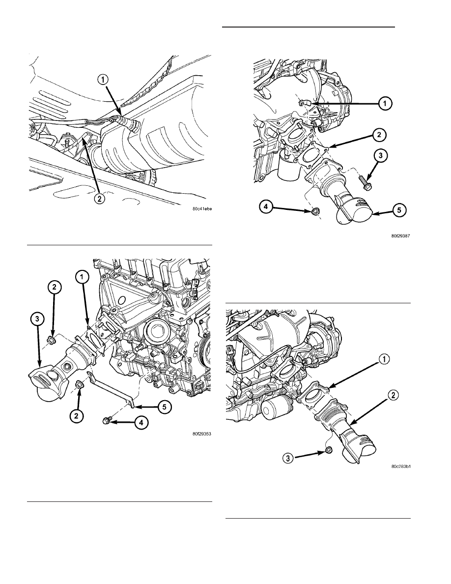
Fig. 8 Downstream 1/2 Oxygen Sensor - Typical

1 - DOWN STREAM O2 SENSOR
2 - UP STREAM O2 SENSOR

Fig. 9 Converter to Exhaust Manifold Connection -

1.6L

1 - GASKET
2 - NUT
3 - CATALYTIC CONVERTER
4 - BOLT
5 - SUPPORT BRACKET

Fig. 10 Converter to Exhaust Manifold Connection -

2.0L

1 - FLAG NUT
2 - GASKET
3 - BOLT
4 - NUT
5 - CATALYTIC CONVERTER

Fig. 11 Converter to Exhaust Manifold Connection -

2.4L

1 - GASKET
2 - CATALYTIC CONVERTER
3 - NUT

11 - 10

EXHAUST SYSTEM AND TURBOCHARGER

PT

CATALYTIC CONVERTER (Continued)

INSPECTION

WARNING: THE NORMAL OPERATING TEMPERA-
TURE OF THE EXHAUST SYSTEM IS VERY HIGH.
THEREFORE, NEVER ATTEMPT TO SERVICE ANY
PART OF THE EXHAUST SYSTEM UNTIL IT IS
COOLED. SPECIAL CARE SHOULD BE TAKEN
WHEN WORKING NEAR THE CATALYTIC CON-
VERTER. THE TEMPERATURE OF THE CONVERTER
RISES TO A HIGH LEVEL AFTER A SHORT PERIOD
OF ENGINE OPERATION TIME.

Check catalytic converter for a flow restriction.

(Refer to 11 - EXHAUST SYSTEM - DIAGNOSIS
AND TESTING) Exhaust System Restriction Check
for procedure.

Visually inspect the catalytic converter element by

using a borescope or equivalent. Remove oxygen sen-
sor(s) and insert borescope. If borescope is not avail-
able, remove converter and inspect element using a
flashlight. Inspect element for cracked or melted sub-
strate.

NOTE: Before replacing a catalytic converter, deter-
mine the root cause of failure. Most catalytic con-
verter failures are caused by air, fuel or ignition
problems. (Refer to Appropriate Diagnostic Informa-
tion) for test procedures.

INSTALLATION

NOTE: When assembling exhaust system do not
tighten clamps until all components are aligned and
clearances are checked.

(1) Assemble catalytic converter to exhaust mani-

fold connection. Use a new flange gasket.

(2) Tighten the catalytic converter to exhaust man-

ifold fasteners to 28 N·m (250 in. lbs.) (Fig. 9), (Fig.
10), (Fig. 11) or (Fig. 12).

(3) Install intermediate pipe and muffler (Refer to

11 - EXHAUST SYSTEM/INTERMEDIATE PIPE -
INSTALLATION).

(4) Working from the front of system; align each

component to maintain position and proper clearance
with underbody parts (Fig. 2). For clearance specifi-
cations (Refer to 11 - EXHAUST SYSTEM - SPECI-
FICATIONS).

(5) Tighten band clamps to 47 N·m (35 ft. lbs.).

CAUTION: Band clamps should never be tightened
such that the two sides of the clamps are bottomed
out against the center hourglass shaped center
block. Once this occurs, the clamp has lost clamp-
ing force and must be replaced.

(6) If removed, install downstream oxygen sensor

(Fig. 8).

(7) Connect downstream oxygen sensor electrical

connector.

(8) 1.6L Engine - Connect upstream oxygen sensor

connector.

(9) Start the engine and inspect for exhaust leaks.

Repair exhaust leaks as necessary.

(10) Check the exhaust system for contact with the

body panels. Make the necessary adjustments, if
needed.

Fig. 12 Converter to Exhaust Manifold Connection -

2.4L Turbo

1 - FLAG NUT
2 - GASKET
3 - NUT
4 - BOLT
5 - CATALYTIC CONVERTER

PT

EXHAUST SYSTEM AND TURBOCHARGER

11 - 11

CATALYTIC CONVERTER (Continued)

SUPPORT BRACKETS AND
ISOLATORS

REMOVAL

(1) Disconnect isolator from exhaust system com-

ponent.

(2) Remove screws attaching isolator bracket to

underbody (Fig. 13).

(3) Remove isolator assembly (Fig. 13).

INSTALLATION

(1) Position isolator bracket to underbody and

install attaching screws (Fig. 13). Tighten bracket
screws to frame rail to 8.5 N·m (75 in. lbs.) and
bracket screws to the rear panel to 3.7 N·m (33 in.
lbs.).

(2) Connect isolator to exhaust system component.
(3) Start the engine and inspect for exhaust leaks.

Repair exhaust leaks as necessary.

(4) Check the exhaust system for contact with the

body panels. Make the necessary adjustments, if
needed.

HEAT SHIELDS

DESCRIPTION

Heat shields (Fig. 14), (Fig. 15), (Fig. 16), and (Fig.

17) are needed to protect both the vehicle and the
environment from the high temperatures developed
in the vicinity of the catalytic converter.

CAUTION: Avoid application of rust prevention com-
pounds or undercoating materials to exhaust sys-
tem floor pan heat shield on cars if equipped. Light
over-spray near the edges is permitted. Application
of coating will greatly reduce the efficiency of the
heat shields resulting in excessive floor pan tem-
peratures and objectionable fumes.

REMOVAL

(1) Raise vehicle on hoist.
(2) Remove fasteners attaching heat shield (Fig.

14), (Fig. 15), (Fig. 16), or (Fig. 17).

(3) Remove heat shield(s).

Fig. 13 Exhaust System Isolator and Bracket

Fig. 14 Heat Shield - Engine Wiring

1 - HEAT SHIELD
2 - NUT
3 - NUT

Fig. 15 Heat Shield - Catalytic Converter

1 - HEAT SHIELD
2 - NUT

11 - 12

EXHAUST SYSTEM AND TURBOCHARGER

PT

INSTALLATION

(1) Position heat shield(s) to underbody.
(2) Install heat shield fasteners (Fig. 14), (Fig. 15),

(Fig. 16), or (Fig. 17).

(3) Inspect heat shield to exhaust system clear-

ances and adjust as necessary (Fig. 2). For clearance
specifications (Refer to 11 - EXHAUST SYSTEM -
SPECIFICATIONS).

(4) Lower vehicle.

(5) Start the engine and inspect for exhaust leaks.

Repair exhaust leaks as necessary.

(6) Check the exhaust system for contact with the

body panels. Make the necessary adjustments, if
needed.

TURBOCHARGER SYSTEM

DIAGNOSIS AND TESTING

DIAGNOSIS AND TESTING - TURBOCHARGER

Check for Diagnostic Trouble Codes (DTC’S) stored

in PCM memory. If any DTC’S are present, refer to
the appropriate Powertrain Diagnostic Information.

TURBOCHARGER DIAGNOSIS

CONDITION

POSSIBLE CAUSES

Low boost pressure, lack
of power

Clogged air filter

Leaks between engine
and turbocharger

Exhaust restriction

Restriction in charge air
cooler hose(s)

Wastegate stuck open

Wastegate actuator
malfunction

Seized turbocharger shaft

Overboost

Wastegate stuck shut

Wastegate actuator
malfunction

Noisy operation or
vibration

Leak(s) in charge air
cooler hose(s)

Intake or exhaust leaks

Oil starvation

Worn turbocharger
bearings

Damaged turbine/
compressor fins

Blue smoke from exhaust

Oil return line blocked

Engine breather clogged

Turbocharger shaft seals
damaged

Fig. 16 Heat Shield - Intermediate Pipe

1 - SCREW
2 - HEAT SHIELD
3 - NUT
4 - SCREW

Fig. 17 Heat Shield - Muffler

1 - HEAT SHIELD
2 - FASTENER

PT

EXHAUST SYSTEM AND TURBOCHARGER

11 - 13

HEAT SHIELDS (Continued)


Content   ..  722  723  724  725   ..