Chrysler PT Cruiser. Manual - part 723
MUFFLER
REMOVAL
WARNING: THE NORMAL OPERATING TEMPERA-
TURE OF THE EXHAUST SYSTEM IS VERY HIGH.
THEREFORE, NEVER WORK AROUND OR ATTEMPT
TO SERVICE ANY PART OF THE EXHAUST SYSTEM
UNTIL IT IS COOLED. SPECIAL CARE SHOULD BE
TAKEN WHEN WORKING NEAR THE CATALYTIC
CONVERTER. THE TEMPERATURE OF THE CON-
VERTER RISES TO A HIGH LEVEL AFTER A SHORT
PERIOD OF ENGINE OPERATING TIME.
(1) Raise vehicle on hoist and apply penetrating oil
to band clamp fastener of component being removed.
NOTE: Do not use petroleum-based lubricants when
removing/installing muffler or exhaust pipe isola-
tors as it may compromise the life of the part. A
suitable substitute is a mixture of liquid dish soap
and water.
(2) Remove exhaust system ground strap at rear of
muffler.
(3) Loosen band clamp and remove support isola-
tors at muffler. Remove muffler from intermediate
pipe (Fig. 3).
(4) Clean ends of pipes and muffler to assure mat-
ing of all parts. Discard broken or worn isolators,
rusted or overused clamps, supports, and attaching
parts.
NOTE: When replacement is required on any com-
ponent of the exhaust system, you must use origi-
nal equipment parts (or their equivalent).
INSTALLATION
When assembling exhaust system do not tighten
clamps until components are aligned and clearances
are checked.
(1) Install the muffler to intermediate pipe and the
isolator supports to the underbody.
(2) Working from the front of system; align each
component to maintain position and proper clearance
with underbody parts (Fig. 2). For clearance specifi-
cations (Refer to 11 - EXHAUST SYSTEM - SPECI-
FICATIONS). Tighten band clamp to 47 N·m (35 ft.
lbs.) (Fig. 4).
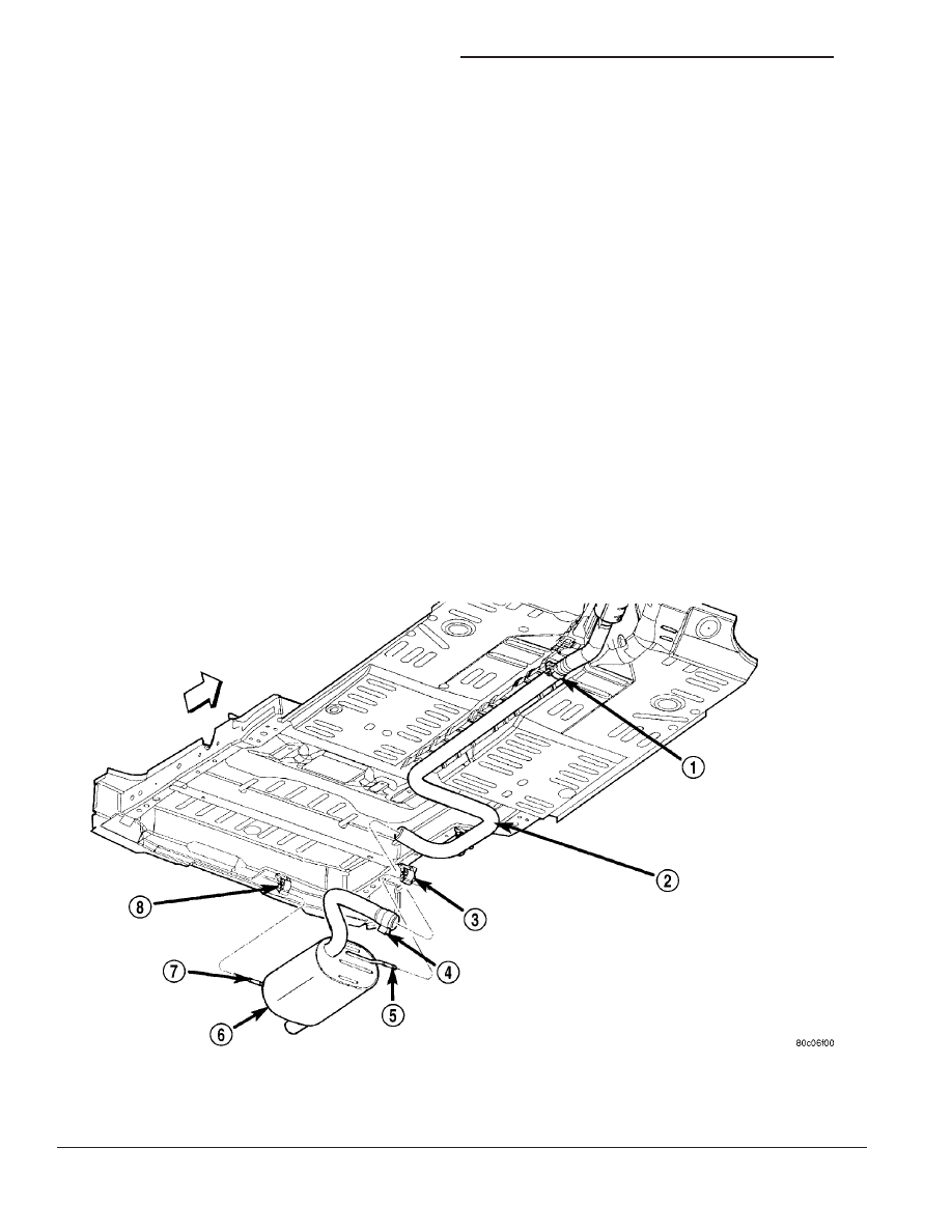
Fig. 3 Muffler
1 - CLAMP
2 - INTERMEDIATE PIPE
3 - ISOLATOR
4 - CLAMP
5 - HANGER
6 - MUFFLER
7 - HANGER
8 - ISOLATOR
11 - 6
EXHAUST SYSTEM AND TURBOCHARGER
PT