Chrysler PT Cruiser. Manual - part 466


  Index      Chrysler     Chrysler PT Cruiser - service repair manual 2005 year


Search            


Content   ..  464  465  466  467   ..


Chrysler PT Cruiser. Manual - part 466


INSTALLATION

Non - Turbo

(1) Install transmission oil cooler and tighten

screws to 8 N·m (70 in. lbs.) (Fig. 3).

NOTE: When the transaxle cooler lines are removed
from the rolled-groove type fittings at the cooler

and transaxle, damage to the inner wall of hose will
occur. To prevent potential leakage, the cooler
hoses and clamps must be replaced.

(2) Replace automatic transmission cooler hoses

and clamps.

(3) Connect hoses to cooler (Fig. 3). Tighten hose

clamps to 2 N·m (18 in. lbs.).

(4) Install front fascia (Refer to 13 - FRAME &

BUMPERS/BUMPERS/FRONT FASCIA - INSTAL-
LATION).

(5) Start engine and check transmission fluid level.

Adjust level as necessary.

Turbo

NOTE: When the transaxle cooler lines are removed
from the rolled-groove type fittings at the cooler
and transaxle, damage to the inner wall of hose will
occur. To prevent potential leakage, the cooler
hoses and clamps must be replaced.

(1) Replace automatic transmission cooler hoses

and clamps.

(2) Connect hoses to cooler. Tighten hose clamps to

2 N·m (18 in. lbs.).

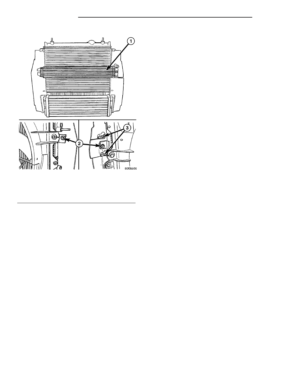
(3) Install transmission oil cooler and tighten

screws to 8 N·m (70 in. lbs.) (Fig. 5).

(4) Install radiator closure panel center brace (Fig.

4).

(5) Install upper radiator closure panel (Refer to

23 - BODY/EXTERIOR/RADIATOR CROSSMEMBER
- INSTALLATION) (Fig. 4).

(6) Install grille (Refer to 23 - BODY/EXTERIOR/

GRILLE - INSTALLATION).

(7) Start engine and check transmission fluid level.

Adjust level as necessary.

Fig. 5 Automatic Transmission Oil Cooler -

Removal/Installation 2.4L Turbo

1 - TRANSMISSION OIL COOLER
2 - ATTACHING SCREWS
3 - HOSE FITTINGS

7 - 66

TRANSMISSION

PT

AUTOMATIC TRANSMISSION OIL COOLER (Continued)

AUDIO/VIDEO

TABLE OF CONTENTS

page

page

AUDIO

DESCRIPTION

. . . . . . . . . . . . . . . . . . . . . . . . . . 1

OPERATION

. . . . . . . . . . . . . . . . . . . . . . . . . . . . 1

DIAGNOSIS AND TESTING - AUDIO

. . . . . . . . . . 2

ANTENNA BODY & CABLE

DESCRIPTION

. . . . . . . . . . . . . . . . . . . . . . . . . . 4

OPERATION

. . . . . . . . . . . . . . . . . . . . . . . . . . . . 4

DIAGNOSIS AND TESTING - ANTENNA BODY

AND CABLE

. . . . . . . . . . . . . . . . . . . . . . . . . . 4

REMOVAL

. . . . . . . . . . . . . . . . . . . . . . . . . . . . . 5

INSTALLATION

. . . . . . . . . . . . . . . . . . . . . . . . . . 6

ANTENNA - EXPORT

REMOVAL

. . . . . . . . . . . . . . . . . . . . . . . . . . . . . 6

INSTALLATION

. . . . . . . . . . . . . . . . . . . . . . . . . . 6

ANTENNA - NAVIGATION

REMOVAL

. . . . . . . . . . . . . . . . . . . . . . . . . . . . . 6

INSTALLATION

. . . . . . . . . . . . . . . . . . . . . . . . . . 6

ANTENNA - SATELLITE RADIO

DESCRIPTION

. . . . . . . . . . . . . . . . . . . . . . . . . . 7

OPERATION

. . . . . . . . . . . . . . . . . . . . . . . . . . . . 7

REMOVAL

. . . . . . . . . . . . . . . . . . . . . . . . . . . . . 7

INSTALLATION

. . . . . . . . . . . . . . . . . . . . . . . . . . 7

ANTENNA CABLE - SATELLITE RADIO

DESCRIPTION

. . . . . . . . . . . . . . . . . . . . . . . . . . 8

REMOVAL

. . . . . . . . . . . . . . . . . . . . . . . . . . . . . 8

INSTALLATION

. . . . . . . . . . . . . . . . . . . . . . . . . . 8

RADIO

DESCRIPTION

. . . . . . . . . . . . . . . . . . . . . . . . . . 8

OPERATION

. . . . . . . . . . . . . . . . . . . . . . . . . . . 11

REMOVAL

. . . . . . . . . . . . . . . . . . . . . . . . . . . . . 11

INSTALLATION

. . . . . . . . . . . . . . . . . . . . . . . . . 12

RADIO NOISE SUPPRESSION COMPONENTS

DESCRIPTION

. . . . . . . . . . . . . . . . . . . . . . . . . 12

OPERATION

. . . . . . . . . . . . . . . . . . . . . . . . . . . 12

REMOVAL

. . . . . . . . . . . . . . . . . . . . . . . . . . . . . 13

INSTALLATION

. . . . . . . . . . . . . . . . . . . . . . . . . 14

SATELLITE RECEIVER MODULE

DESCRIPTION

. . . . . . . . . . . . . . . . . . . . . . . . . 15

OPERATION

. . . . . . . . . . . . . . . . . . . . . . . . . . . 15

REMOVAL

. . . . . . . . . . . . . . . . . . . . . . . . . . . . . 15

INSTALLATION

. . . . . . . . . . . . . . . . . . . . . . . . . 15

SPEAKER

REMOVAL

. . . . . . . . . . . . . . . . . . . . . . . . . . . . . 16

INSTALLATION

. . . . . . . . . . . . . . . . . . . . . . . . . 17

AUDIO

DESCRIPTION

Several combinations of radio receivers are offered.

The audio system uses an ignition switched source of
battery current so that the system will only operate
when the ignition switch is in the RUN or ACCES-
SORY positions.

An optional navigation radio (RB3) is available on

this vehicle. With this system, the operator has the
option of choosing a street address, point of interest,
trip itinerary and other features outlined in the oper-
ator’s manual.

The audio system includes the following compo-

nents:

• Antenna

• Antenna - satellite radio (if equipped)

• Radio noise suppression components

• Radio receiver

• Satellite receiver module (if equipped)

• Speakers
Certain functions and features of the audio system

rely upon resources shared with other electronic
modules in the vehicle over the Programmable Com-
munication Interface (PCI) bus network. The data

bus network allows the sharing of sensor informa-
tion. For diagnosis of these electronic modules or of
the data bus network, the use of a DRB III

t scan tool

and the proper Diagnostic Procedures manual are
recommended.

OPERATION

The audio system components are designed to pro-

vide audio entertainment and information through
the reception, tuning and amplification of locally
broadcast radio signals in both the Amplitude Modu-
lating (AM) and Frequency Modulating (FM) com-
mercial frequency ranges.

The available satellite radio system is a subscrip-

tion based service. Information sent by satellite is
transmitted to the roof mounted antenna, then to the
satellite receiver module. The operator then has the
choice of multiple music/information channels.

The available navigation radio system receives

GPS signals from up to eight satellites to display the
position and direction of the vehicle. Map information
is supplied through a DVD-ROM. An electronic gyro-
sensor and the vehicle’s speed sensor enable the sys-
tem to display the present vehicle position even in
locations where GPS signals may be blocked.

PT

AUDIO/VIDEO

8A - 1

When a destination is selected, the navigation sys-

tem uses information from the map to quickly calcu-
late a route. As the vehicle is driven along the chosen
route, the operator is guided with pictorial displays
and voice prompts. For complete operating instruc-
tions, refer to the manual included with the vehicle.

The audio system components operate on battery

current received through a fuse in the Junction Block
(JB) on a fused ignition switch output (run-acc) cir-
cuit so that the system will only operate when the
ignition switch is in the On or Accessory positions.

DIAGNOSIS AND TESTING - AUDIO

Any diagnosis of the Audio system should

begin with the use of the DRB III

diagnostic

tool. For information on the use of the DRB
III

t, refer to the appropriate Diagnostic Service

information.

For complete circuit diagrams, refer to the appro-

priate wiring information.

WARNING:

DISABLE

THE

AIRBAG

SYSTEM

BEFORE ATTEMPTING ANY STEERING WHEEL,
STEERING COLUMN, SEAT BELT TENSIONER, SIDE
AIRBAG, OR INSTRUMENT PANEL COMPONENT
DIAGNOSIS OR SERVICE. DISCONNECT AND ISO-
LATE THE BATTERY NEGATIVE (GROUND) CABLE,
THEN WAIT TWO MINUTES FOR THE AIRBAG SYS-
TEM CAPACITOR TO DISCHARGE BEFORE PER-
FORMING FURTHER DIAGNOSIS OR SERVICE. THIS
IS THE ONLY SURE WAY TO DISABLE THE AIRBAG
SYSTEM. FAILURE TO TAKE THE PROPER PRE-
CAUTIONS COULD RESULT IN ACCIDENTAL AIR-
BAG DEPLOYMENT AND POSSIBLE PERSONAL
INJURY.

AUDIO SYSTEM DIAGNOSIS

CONDITION

POSSIBLE CAUSES

CORRECTION

NO AUDIO

1. Fuse inoperative.

1. Check radio fuse and Ignition-Off Draw (IOD)
fuse in Junction Block (JB). Replace fuses, if
required.

2. Radio connector
damaged.

2. Check for loose or corroded radio connector.
Repair, if required.

3. Wiring damaged.

3. Check for shorted or open wires. Repair wiring,
if required.

4. Radio ground damaged.

4. Check for continuity between radio chassis and
a known good ground. There should be
continuity. Repair ground, if required.

5. Radio inoperative.

5. Refer to appropriate Diagnostic Service
information.

6. Speakers inoperative.

6. Replace speaker as necessary.

NO SATELLITE RADIO
AUDIO (PERFORM ALL
DIAGNOSIS OUTDOORS)

1. Subscription service has
expired (with subscription
expired, one channel is still
available)

1. Contact satellite radio provider.

2. Items on roof blocking
satellite antenna.

2. Remove or reposition items to allow clear
space around antenna.

3. Damaged satellite antenna
cable.

3. Replace satellite antenna cable.

3. Damaged satellite
antenna.

3. Replace satellite antenna.

NO RADIO DISPLAY

1. Fuse inoperative.

1. Check radio fuse and Ignition-Off Draw (IOD)
fuse in Junction Block (JB). Replace fuses, if
required.

2. Radio connector
damaged.

2. Check for loose or corroded radio connector.
Repair, if required.

3. Wiring damaged.

3. Check for battery voltage at radio connector.
Repair wiring, if required.

8A - 2

AUDIO/VIDEO

PT

AUDIO (Continued)

CONDITION

POSSIBLE CAUSES

CORRECTION

4. Radio ground damaged.

4. Check for continuity between radio chassis and
a known good ground. There should be
continuity. Repair ground, if required.

5. Radio inoperative.

5. Refer to appropriate Diagnostic Service
information.

CLOCK WILL NOT KEEP
SET TIME

1. Fuse inoperative.

1. Check Ignition-Off Draw (IOD) fuse in the
Junction Block (JB). Replace fuse, if required.

2. Radio connector
damaged.

2. Check for loose or corroded radio connector.
Repair, if required.

3. Wiring damaged.

3. Check for battery voltage at radio connector.
Repair wiring, if required.

4. Radio ground damaged.

4. Check for continuity between radio chassis and
a known good ground. There should be
continuity. Repair ground, if required.

5. Radio inoperative.

5. Refer to appropriate Diagnostic Service
information.

SOUND DISTORTION
(VIBRATION FROM
SPEAKER AREA, BUZZING -
HUMMING)

1. Door trim panel loose or
missing fasteners.

1. Inspect door trim panel and correct as
necessary. Replace any missing fasteners.

2. Water shield loose or
misaligned.

2. Inspect water shield and adjust as required.

3. Items placed in door trim
panel map pockets vibrating
or moving from side to side.

3. Remove items from door trim panel. Ensure
that vibration is no longer present.

POOR RADIO RECEPTION

1. Antenna damaged or
inoperative.

1. Diagnose and replace antenna if necessary.

2. Radio ground damaged.

2. Check for continuity between radio chassis and
a known good ground. There should be
continuity. Repair ground, if required.

3. Radio noise suppression
inoperative.

3. Repair or replace ground strap as necessary.

4. Radio inoperative.

4. Refer to appropriate Diagnostic Service
information.

NO/POOR TAPE
OPERATION

1. Damaged tape.

1. Insert known good tape and test operation.

2. Foreign objects behind
tape door.

2. Remove foreign objects and test operation.

3. Dirty cassette tape head.

3. Clean head with Mopar Cassette Head
Cleaner.

4. Inoperative radio.

4. Exchange or replace radio, if required.

NO COMPACT DISC
OPERATION

1. Damaged CD.

1. Insert known good CD and test operation.

2. Foreign material on CD.

2. Clean CD and test operation.

3. Condensation on CD or
optics.

3. Allow temperature of vehicle interior to stabilize
and test operation.

4. Inoperative radio.

4. Refer to appropriate Diagnostic Service
information.

PT

AUDIO/VIDEO

8A - 3

AUDIO (Continued)


Content   ..  464  465  466  467   ..