Chrysler PT Cruiser. Manual - part 415


  Index      Chrysler     Chrysler PT Cruiser - service repair manual 2005 year


Search            


Content   ..  413  414  415  416   ..


Chrysler PT Cruiser. Manual - part 415


INSTALLATION

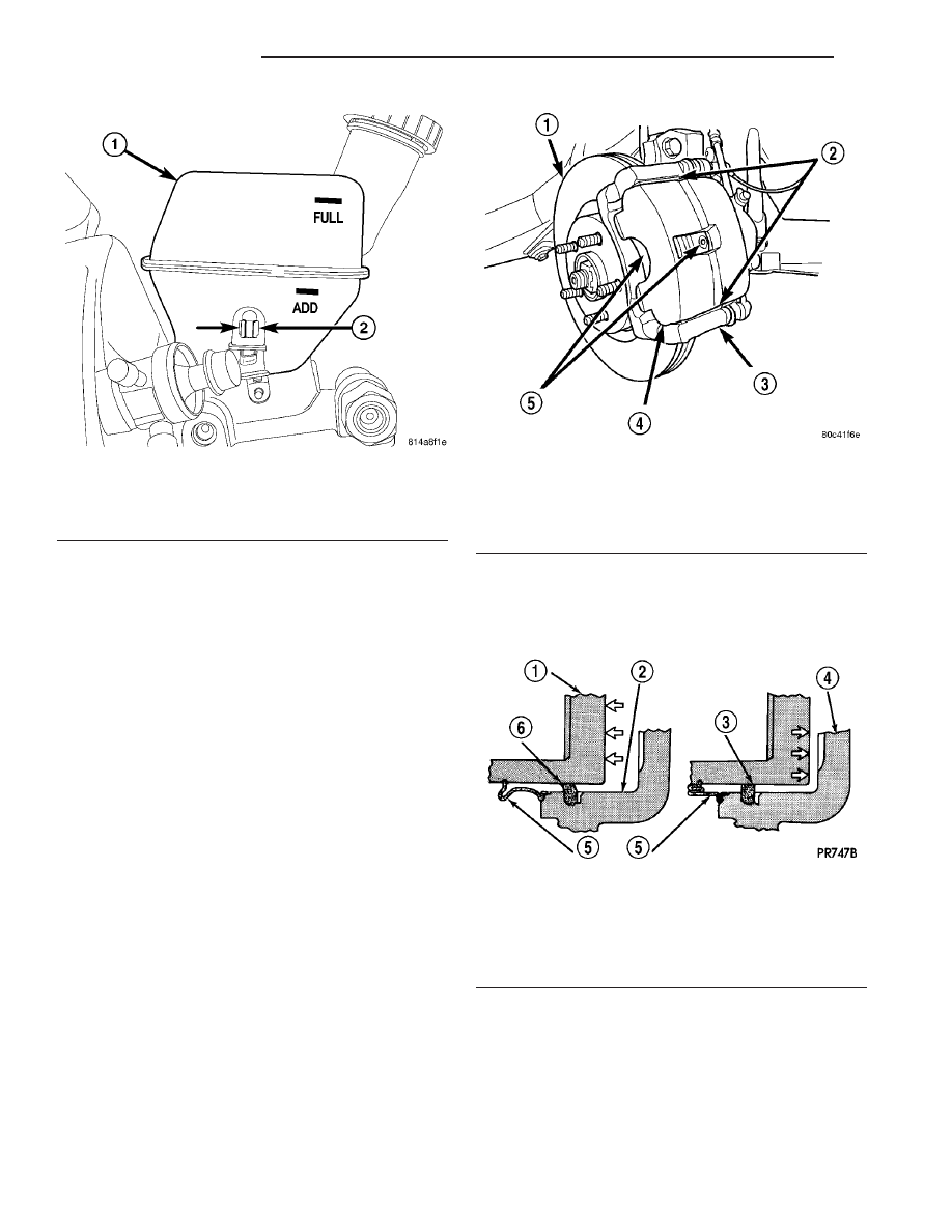
(1) Align the brake fluid level switch with its

mounting hole on the left side of the master cylinder
brake fluid reservoir. Push the switch into the fluid
reservoir

until

the

switch

retaining

tabs

are

expanded on the other side of the reservoir, locking it
in place (Fig. 5) (Fig. 6).

(2) Connect the brake fluid level switch wiring

connector (Fig. 4).

HYDRAULIC/MECHANICAL

DESCRIPTION

DESCRIPTION - DISC BRAKES (FRONT)

Each front disc brake assembly consists of the fol-

lowing components (Fig. 7):

• Caliper - single-piston, floating type

• Caliper adapter

• Shoe and lining assemblies

• Rotor
The caliper is a one-piece casting with the inboard

side containing a single piston cylinder bore. The
front disc brake caliper piston, is manufactured from
a phenolic compound. The outside diameter of the
caliper piston is 57 mm.

A square-cut rubber piston seal is located in a

machined groove in the caliper cylinder bore. This
seal provides a hydraulic seal between the piston and
the cylinder wall (Fig. 8).

A rubber dust boot is installed in a groove in cyl-

inder bore opening and in a groove in the piston (Fig.
9). The boot prevents contamination in the bore area.

Fig. 6 Fluid Level Switch Retaining Tabs -

Continental Teves

1 - RESERVOIR
2 - FLUID LEVEL SWITCH RETAINING TABS

Fig. 7 Front Disc Brakes

1 - BRAKE ROTOR
2 - ABUTMENT SHIMS
3 - DISC BRAKE ADAPTER
4 - CALIPER
5 - BRAKE SHOES (PADS)

Fig. 8 Piston Seal Function

1 - PISTON
2 - CYLINDER BORE
3 - PISTON SEAL BRAKE PRESSURE OFF
4 - CALIPER HOUSING
5 - DUST BOOT
6 - PISTON SEAL BRAKE PRESSURE ON

5 - 12

BRAKES - BASE

PT

BRAKE FLUID LEVEL SWITCH (Continued)

The caliper is mounted to the caliper adapter using

two guide pin bolts. These bolts thread into two
guide pins, slid into the adapter (Fig. 10). The pins
are lubricated and have boots to seal them in place
in the adapter.

The disc brake caliper adapter is fastened to the

steering knuckle using two bolts (Fig. 11).

The machined abutments on the adapter position

the brake shoes and caliper. There are two brake
shoes, sometimes referred to as pads, per disc brake.
One shoe is placed on each side of the brake rotor
(Fig. 12). Two abutment shims (upper and lower) ride
between the shoes and adapter. The shoes have
springs permanently attached to them to help main-
tain a distance between the shoes and the caliper.
When brake shoes are replaced, only brake shoes
meeting the original equipment manufacturer (OEM)
formulation (such as Mopar

t replacement parts)

should be used.

Front disc brakes are equipped with audible wear

indicators on the inboard brake shoes.

Each front brake rotor is vented to help cool it dur-

ing and after brake applications. It is mounted on
the studs of the front wheel bearing hub.

Fig. 9 Piston Boot Installation

Fig. 10 Adapter, Boots And Pins

1 - PINS
2 - BOOTS

Fig. 11 Adapter Mounting

1 - BRAKE HOSE
2 - ADAPTER MOUNTING BOLTS
3 - BANJO BOLT
4 - CALIPER GUIDE PIN BOLTS

Fig. 12 Brake Shoes Mounted In Adapter

1 - SPRINGS
2 - INBOARD SHOE
3 - OUTBOARD SHOE
4 - DISC BRAKE ADAPTER
5 - ABUTMENT SHIMS
6 - BRAKE ROTOR

PT

BRAKES - BASE

5 - 13

HYDRAULIC/MECHANICAL (Continued)

This vehicle has an optional performance brake

system. The sales code for this system is BR4.
Although similar in appearance to the other front
disc brake systems available (BRB and BRK (Disc/
Drum combination) and BRT (Disc/Disc combina-
tion)), this system features heavy duty wheel brake
components. BR4 front disc brakes utilize brake
rotors that have a pad contact surface approximately
5 mm thicker and brake calipers (and adapters) to
accommodate that additional width. The BR4 cali-
pers and rotors can be easily identified. Each BR4
brake caliper is marked “Turbo” while each rotor has
a recessed machined area near the hub center (Fig.
13) (Fig. 14).

NOTE: Special care should be taken to assure that
the correct caliper is used only with the correct
rotor.

DESCRIPTION - DISC BRAKES (REAR)

Rear disc brakes are optional equipment on some

models of this vehicle (Fig. 15). The rear disc brakes
are similar to the front disc brakes; however, there
are several distinctive features that require different
service procedures. Each rear disc brake consists of
the following components:

• Caliper - single-piston, floating type

• Caliper adapter

• Shoe and lining assemblies

• Rotor - drum-in-hat type
Vehicles are equipped with a one piece caliper

assembly that has a 36 mm (1.42 in.) piston and uses
a solid non-vented 270 mm (10.63 in.) brake rotor.

The caliper assembly for all applications floats on

rubber bushings using internal metal sleeves that

are attached to the adapter using threaded guide pin
bolts.

The brake caliper adapter is mounted to the rear

suspension spindle. The adapter is used to mount the
disc brake caliper to the vehicle (Fig. 15). The
adapter has two machined abutments which are used
to position and align the caliper and brake shoes for
movement inboard and outboard.

When brake shoes, sometimes referred to as pads,

are replaced, only brake shoes meeting the original
equipment manufacturer (OEM) formulation (such as
Mopar

t replacement parts) should be used.

The adapter also mounts the parking brake shoes

and actuating cables to the vehicle. All vehicles
equipped with rear disc brakes have a small duo-
servo drum brake mounted to the caliper adapter.
This is part of the parking brake system. (Refer to 5
- BRAKES/PARKING BRAKE - DESCRIPTION)

This vehicle has an optional performance brake

system. The sales code for this system is BR4.
Although similar in appearance to the BRT (Disc/

Fig. 13 Standard And BR4 Brake Calipers

1 - BRB/BRT FRONT BRAKE CALIPER
2 - ADAPTER
3 - ADAPTER
4 - BR4 FRONT BRAKE CALIPER

Fig. 14 Front Brake Rotor Comparison

1 - BRB/BRT BRAKE ROTOR
2 - STANDARD ROTOR THICKNESS
22.91-23.10 MM
3 - PERFORMANCE ROTOR THICKNESS
27.91-28.10 MM
4 - BR4 PERFORMANCE BRAKE ROTOR
5 - INDENTIFYING MACHINED AREA

5 - 14

BRAKES - BASE

PT

HYDRAULIC/MECHANICAL (Continued)

Disc combination), this system features heavy duty
wheel brake components. BR4 rear disc brakes uti-
lize brake rotors that have a pad contact surface
approximately 3 mm thicker. To accommodate that
additional width, instead of using wider calipers as
the front brakes do, each rear brake shoe metal back-
ing plate is 1.5 mm thinner than that of the standard
BRT rear disc brakes (Fig. 16). BR4 brake rotors can
be easily identified by the recessed machined area
near the hub center (Fig. 17).

NOTE: Special care should be taken to assure that
the correct brake shoes are used only with the cor-
rect rotor.

DESCRIPTION - DRUM BRAKES (REAR)

All vehicles with rear drum brakes are equipped

with 228mm rear drum brakes sales code designated
BRB or BRK. The drum brakes are all two-shoe,
internal-expanding type with an automatic adjuster
screw.

The rear drum brake system consists of these

major components (Fig. 18) as well as the attaching
hardware:

• Drum

• Shoes

• Support Plate

• Wheel Cylinder

Fig. 15 Rear Disc Brakes

1 - DISC BRAKE ADAPTER
2 - GUIDE PIN BOLTS
3 - HUB AND BEARING
4 - BRAKE ROTOR
5 - RETAINER CLIP
6 - DUST CAP
7 - NUT
8 - DISC BRAKE CALIPER

Fig. 16 Standard And BR4 Brake Shoes

1 - BRAKE CALIPER WITH BRT SHOES
2 - BRAKE CALIPER WITH BR4 SHOES
3 - 4.5 MM
4 - 6.0 MM

Fig. 17 Rear Brake Rotor Comparison

1 - BRT BRAKE ROTOR
2 - STANDARD ROTOR THICKNESS
8.75-9.25 MM
3 - PERFORMANCE ROTOR THICKNESS
11.75-12.25 MM
4 - BR4 PERFORMANCE BRAKE ROTOR
5 - INDENTIFYING MACHINED AREA

PT

BRAKES - BASE

5 - 15

HYDRAULIC/MECHANICAL (Continued)


Content   ..  413  414  415  416   ..