Chrysler PT Cruiser. Manual - part 411
CAUTION:
The
following
positioning
procedure
determines the correct air pressure inside the inner
tripod joint assembly prior to clamping the sealing
boot to inner tripod joint housing. If this procedure
is not done prior to clamping sealing boot to tripod
joint housing, boot durability can be adversely
affected.
CAUTION: When venting the inner tripod joint
assembly, use care so inner tripod sealing boot
does not get punctured or, in any other way, dam-
aged. If sealing boot is punctured or damaged while
being vented, the sealing boot can not be used.
(9) Insert a trim stick between the tripod joint and
the sealing boot to vent inner tripod joint assembly
(Fig. 43). When inserting trim stick between tri-
pod housing and sealing boot, ensure trim stick
is held flat and firmly against the tripod hous-
ing. If this is not done, damage to the sealing
boot can occur. If inner tripod joint has a Hytrel
(hard plastic) sealing boot, be sure trim stick is
inserted between soft rubber insert and tripod hous-
ing, and not the hard plastic sealing boot and soft
rubber insert.
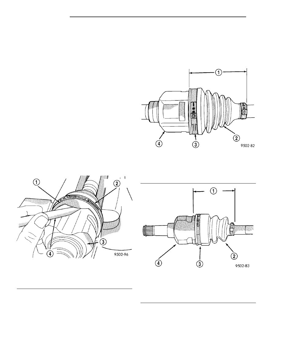
(10) With trim stick inserted between sealing boot
and tripod joint housing, position inner tripod joint
on halfshaft until correct sealing boot edge to edge
length is obtained for type of sealing boot material
being used (Fig. 44) (Fig. 45). Then remove the trim
stick.
Fig. 43 Trim Stick Inserted for Venting Tripod Joint
1 - INNER TRIPOD JOINT SEALING BOOT
2 - SEALING BOOT CLAMP
3 - INNER TRIPOD JOINT HOUSING
4 - TRIM STICK
Fig. 44 Sealing Boot End to End Length with Hytrel
Boot
1 - 107 MILLIMETERS
2 - HYTREL SEALING BOOT
3 - SEALING BOOT CLAMP
4 - INNER TRIPOD JOINT
Fig. 45 Sealing Boot End to End Length with
Silicone Boot
1 - 105 MILLIMETERS
2 - SILICONE SEALING BOOT
3 - CLAMP
4 - INNER TRIPOD JOINT
3 - 18
HALF SHAFT
PT
CV BOOT - INNER (Continued)