Chrysler PT Cruiser. Manual - part 396


  Index      Chrysler     Chrysler PT Cruiser - service repair manual 2005 year


Search            


Content   ..  394  395  396  397   ..


Chrysler PT Cruiser. Manual - part 396


(3) Clean the threads of the stabilizer bar link

bolts, then apply Mopar

t Lock And Seal or equiva-

lent to the threads.

(4) Install both stabilizer bar links back on vehicle

(Fig. 36). Start each stabilizer bar link bolt with
bushing from the bottom, through the stabilizer bar,
inner link bushings, lower control arm, and into the
upper retainer/nut and bushing (Fig. 1). Do not fully
tighten the link assemblies at this time.

(5) Lower the vehicle.

NOTE: It may be necessary to put the vehicle on a
platform hoist or alignment rack to gain access to
the stabilizer bar mounting bolts with the vehicle at
curb height.

(6) Tighten each stabilizer bar link by holding the

upper retainer/nut with a wrench and turning the
link bolt. Tighten each link bolt to a torque of 29
N·m (260 in. lbs.).

(7) Tighten the stabilizer bar cushion retainer

bolts to a torque of 25 N·m (220 in. lbs.).

STRUT ASSEMBLY

DESCRIPTION

A Macpherson type design strut assembly is used

in place of the front suspension upper control arm
and upper ball joint (Fig. 1). The bottom of the strut
mounts directly to the steering knuckle using 2
attaching bolts and nuts going through the strut cle-
vis bracket and steering knuckle. The top of the strut
mounts directly to the strut tower of the vehicle

using the three threaded studs on the strut assem-
blies upper mount.

The strut assembly includes the following compo-

nents (Fig. 1):

• Upper mount (rubber isolated)

• Upper spring seat and bearing

• Dust shield

• Jounce bumper

• Coil spring

• Lower spring isolator

• Strut (damper)
Each component is serviced by removing the strut

assembly from the vehicle and disassembling it.

Coil springs are rated separately for each corner or

side of the vehicle depending on optional equipment
and type of vehicle service. If a coil spring requires
replacement, be sure that it is replaced with a spring
meeting the correct load rating for the vehicle and its
specific options.

OPERATION

The strut assembly cushions the ride of the vehicle,

controlling vibration, jounce and rebound of the sus-
pension.

The coil spring controls ride quality and maintains

proper ride height.

The spring isolators isolate the coil spring at the

top and bottom from coming into metal-to-metal con-
tact with the upper mounting seat and the strut.

The jounce bumper limits suspension travel and

metal-to-metal contact under full jounce condition.

The strut dampens jounce and rebound motions of

the coil spring and suspension.

DIAGNOSIS AND TESTING - STRUT ASSEMBLY
(FRONT)

Inspect the strut assembly for the following condi-

tions (Fig. 39):

• Inspect for a damaged or broken coil spring.

• Inspect for a torn or damaged strut assembly

dust shield.

• Lift the dust shield and inspect the strut assem-

bly for evidence of fluid running from the upper end
of the strut fluid reservoir. (Actual leakage will be a
stream of fluid running down the side and dripping
off lower end of unit). A slight amount of seepage
between the strut shaft and strut shaft seal is not
unusual and does not affect performance of the strut
assembly.

• Lift the dust shield and inspect the jounce

bumper for signs of damage or deterioration.

• Inspect the clearance between the shock tower

and the coil spring. Make sure no fasteners are pro-
truding through the shock tower possibly contacting
the coil spring and strut. Because of the minimum
clearance in this area (Fig. 38), installation of metal

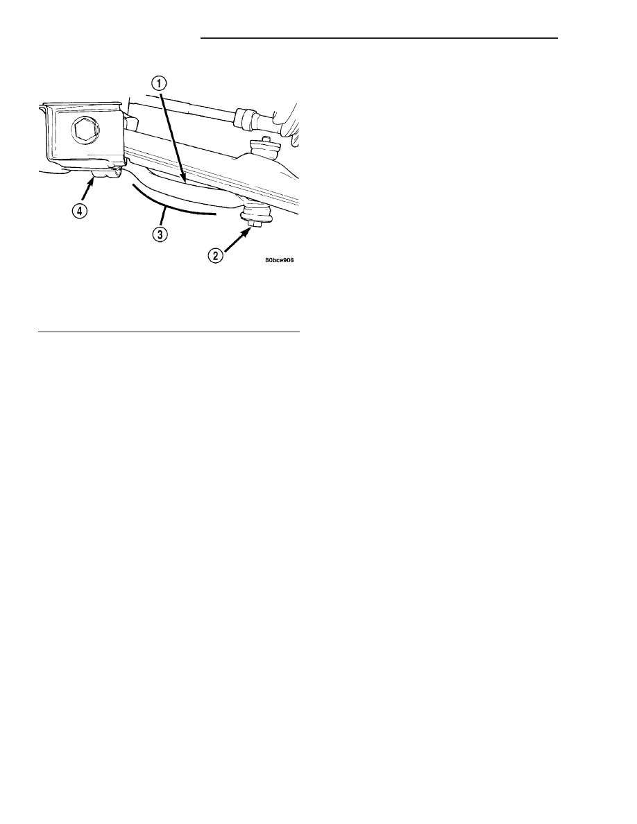
Fig. 37 Downward Curve

1 - STABILIZER BAR
2 - LINK
3 - DOWNWARD CURVE
4 - CUSHION RETAINER

2 - 20

FRONT SUSPENSION

PT

STABILIZER BAR (Continued)

fasteners could damage the coil spring coating and
lead to a corrosion failure of the spring.

CAUTION: At no time when servicing a vehicle can
a sheet metal screw, bolt or other metal fastener be
installed into the shock tower to take the place of
an original plastic clip. Also, do not drill holes into
the front shock tower for the installation of any
metal fasteners into the shock tower area indicated
(Fig. 38).

REMOVAL

NOTE: Before proceeding, (Refer to 2 - SUSPEN-
SION/FRONT - WARNING).

(1) Raise the vehicle. (Refer to LUBRICATION &

MAINTENANCE/HOISTING - STANDARD PROCE-
DURE)

(2) Remove tire and wheel assembly.
(3) If both strut assemblies are to be removed,

mark the strut assemblies right or left according to
which side of the vehicle they were removed from.

(4) Remove the screw securing the ground strap to

the rear of the strut (Fig. 40).

(5) If the vehicle is equipped with Antilock brakes

(ABS), remove the screw securing the ABS wheel
speed sensor to the rear of the strut (Fig. 40).

CAUTION: The strut assembly-to-steering knuckle
attaching bolts are serrated and must not be turned
during removal. Hold the bolts stationary in the
steering knuckle while removing the nuts, then tap
the bolts out using a pin punch.

Fig. 38 Shock Tower Area (Typical)

1 - SHOCK TOWER
2 - COIL SPRING
3 - NO SHEET METAL SCREWS, BOLTS, OR ANY OTHER METAL
FASTENERS ARE TO BE INSTALLED INTO SHOCK TOWER IN
THIS AREA. ALSO, NO HOLES ARE TO BE DRILLED INTO
SHOCK TOWER IN THIS SAME AREA.

Fig. 39 Strut Assembly

1 - NUT
2 - STRUT ASSEMBLY
3 - STRUT
4 - LOWER SPRING ISOLATOR
5 - COIL SPRING
6 - JOUNCE BUMPER
7 - DUST SHIELD
8 - SPRING SEAT AND BEARING (WITH SPRING ISOLATOR)
9 - UPPER MOUNT

Fig. 40 Ground Strap And ABS Sensor Bracket

1 - ABS WHEEL SPEED SENSOR ROUTING BRACKET (IF
EQUIPPED)
2 - GROUND STRAP
3 - GROUND STRAP SCREW
4 - ABS SENSOR BRACKET SCREW (IF EQUIPPED)

PT

FRONT SUSPENSION

2 - 21

STRUT ASSEMBLY (Continued)

(6) Remove the two bolts attaching the strut to the

steering knuckle (Fig. 1).

(7) Lower the vehicle just enough to open the

hood, but without letting the tires touch the floor.

(8) Remove the three nuts attaching the upper

mount of the strut assembly to the vehicle’s strut
tower (Fig. 41).

(9) Remove the strut assembly from the vehicle.
(10) For disassembly, (Refer to 2 - SUSPENSION/

FRONT/STRUT - DISASSEMBLY).

DISASSEMBLY

The Strut assembly must be removed from the

vehicle for it to be disassembled and assembled.
(Refer

to

2

-

SUSPENSION/FRONT/STRUT

-

REMOVAL)

For the disassembly and assembly of the strut

assembly, use strut spring compressor, Pentastar Ser-
vice Equipment (PSE) tool W-7200, or the equivalent,
to compress the coil spring. Follow the manufactur-
er’s instructions closely.

(1) If both struts are being serviced at the same

time, mark the coil spring and strut assembly accord-
ing to which side of the vehicle the strut was
removed from, and which strut the coil spring was
removed from.

(2) Position the strut assembly in the strut coil

spring

compressor

following

the

manufacturers

instructions. Set the lower hooks (Fig. 42), then set
the upper hooks (Fig. 43). Position the strut clevis
bracket straight outward away from the compressor.
Place a clamp on the lower end of the coil spring, so
the strut is held in place once the strut shaft nut is
removed (Fig. 42).

WARNING: DO NOT REMOVE THE STRUT SHAFT
NUT BEFORE THE COIL SPRING IS COMPRESSED.
THE COIL SPRING IS HELD UNDER PRESSURE
AND MUST BE COMPRESSED, REMOVING SPRING
TENSION FROM THE UPPER MOUNT AND PIVOT
BEARING, BEFORE THE SHAFT NUT IS REMOVED.

(3) Compress the coil spring until all coil spring

tension is removed from the upper mount.

CAUTION: Never use impact or high speed tools to
remove the strut shaft nut. Damage to the strut
internal bearings may occur.

(4) Once the spring is sufficiently compressed,

install Strut Nut Socket, Special Tool 6864, on the
strut shaft retaining nut (Fig. 44). Next, install a
socket on the hex on the end of the strut shaft. While
holding the strut shaft from turning, remove the nut
from the strut shaft.

(5) Remove the upper mount from the strut shaft

(Fig. 45).

Fig. 41 Upper Mounting Nuts

1 - NUTS

Fig. 42 Strut Assembly In Compressor (Lower)

1 - LOWER HOOKS
2 - CLAMP
3 - STRUT ASSEMBLY
4 - CLEVIS BRACKET
5 - SPRING COMPRESSOR

2 - 22

FRONT SUSPENSION

PT

STRUT ASSEMBLY (Continued)

(6) Remove the upper spring seat and bearing,

along with the upper spring isolator as an assembly
from the top of the coil spring by pulling them
straight up (Fig. 45). The upper spring isolator can
be separated from the spring seat and bearing once
removed from vehicle.

(7) Remove the dust shield, then the jounce

bumper from the strut shaft by pulling each straight
up (Fig. 45).

(8) Remove the clamp from the bottom of the coil

spring and remove the strut out through the bottom
of the coil spring.

(9) Remove the lower spring isolator from the

lower spring seat on the strut.

NOTE: If the coil spring needs to be serviced, pro-
ceed with the next step, otherwise, proceed with
step Step 11.

Fig. 43 Strut Assembly In Compressor (Upper)

1 - NOTCH IN UPPER SEAT
2 - UPPER MOUNT
3 - UPPER HOOKS
4 - CLEVIS BRACKET

Fig. 44 Shaft Nut Removal/Installation

1 - SPRING COMPRESSOR
2 - SPECIAL TOOL 6864
3 - UPPER MOUNT

Fig. 45 Strut Assembly Components

1 - NUT
2 - STRUT ASSEMBLY
3 - STRUT
4 - LOWER SPRING ISOLATOR
5 - COIL SPRING
6 - JOUNCE BUMPER
7 - DUST SHIELD
8 - SPRING SEAT AND BEARING (WITH SPRING ISOLATOR)
9 - UPPER MOUNT

PT

FRONT SUSPENSION

2 - 23

STRUT ASSEMBLY (Continued)


Content   ..  394  395  396  397   ..