Chrysler PT Cruiser. Manual - part 213


  Index      Chrysler     Chrysler PT Cruiser - service repair manual 2005 year


Search            


Content   ..  211  212  213  214   ..


Chrysler PT Cruiser. Manual - part 213


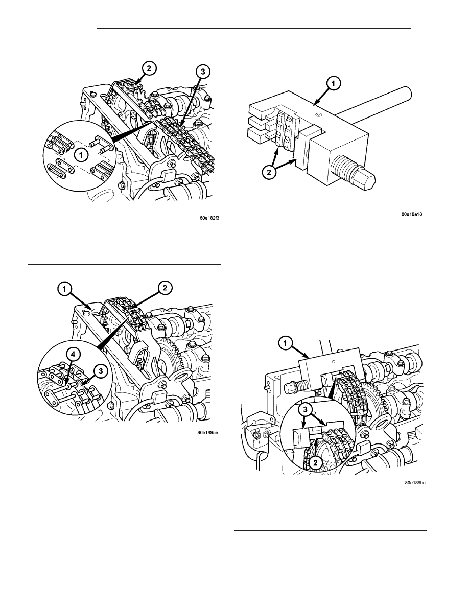
NOTE: When assembling riveting tool, piece F5 is
secured by a screw and D9 can move loosely on
thrust spindle

(8) Assemble riveting tool by inserting pieces F5

and D9 (Fig. 59).

NOTE: Ensure that the riveted link and riveting tool
are aligned.

(9) Press in new riveted link as far as the stop

(Fig. 60).

Fig. 57 Removing Temporary Link

1 - TEMPORARY LINK
2 - NEW TIMING CHAIN
3 - OLD TIMING CHAIN

Fig. 58 Insert New Riveted Link

1 - SPECIAL TOOL #8931
2 - NEW TIMING CHAIN ENDS
3 - NEW MIDDLE PLATE
4 - NEW RIVETED LINK

Fig. 59 Installing Assembly Inserts into Riveting

Tool

1 - SPECIAL TOOL #8947
2 - SPECIAL TOOL #8952

Fig. 60 PRESSING IN NEW RIVETED LINK

1 - SPECIAL TOOL #8947
2 - NEW RIVETED LINK
3 - SPECIAL TOOL #8952

9 - 48

ENGINE

PT

TIMING CHAIN (Continued)

(10) Remove riveting tool to change inserts.
(11) Install insert F1 on riveting tool and secure

with screw (Fig. 61).

(12) Install insert D8 on riveting tool (Fig. 61).

NOTE: The outer plate is held magnetically by rivet-
ing tool.

(13) Insert new outer plate into the moving assem-

bly insert.

(14) Position riveting tool so that spacer webs of

the guide are side by side.

(15) Ensure that riveted link and outer plate are

aligned (Fig. 62).

NOTE: When turning spindle of riveting tool, be
sure that pins of riveted link are inserted into holes
of outer plate (Fig. 62).

(16) Screw in spindle of riveting tool until firm

resistance is felt (Fig. 62).

(17) Remove riveting tool.
(18) Turn over moving assembly insert (D8) to the

riveting profile.

(19) Position riveting tool exactly over middle of

pin.

(20) Tighten riveting tool spindle to end of travel.
(21) Repeat procedure for both riveting pins (Fig.

63).

(22) Inspect riveting, rerivet if required (Fig. 64).
(23) Install camshaft sprocket with timing chain

retained onto camshaft. Tighten camshaft bolts to
18N·m (159 lbs.in.).

(24) Remove camshaft sprocket to timing chain tie

straps.

(25) Install cylinder head front cover and guide

rail (Refer to 9 - ENGINE/CYLINDER HEAD -
INSTALLATION).

(26) Install timing chain tensioner (Refer to 9 -

ENGINE/VALVE

TIMING/TIMING

BELT/CHAIN

AND SPROCKETS - INSTALLATION).

(27) Install cylinder head cover (Refer to 9 -

ENGINE/CYLINDER

HEAD/CYLINDER

HEAD

COVER(S) - INSTALLATION).

(28) Install engine cover (Refer to 9 - ENGINE -

INSTALLATION).

Fig. 61 Installing Riveting Inserts Into Riveting Tool

1 - SPECIAL TOOL #8947
2 - SPECIAL TOOL #8949

Fig. 62 Installing Link Outer Plate

1 - SPECIAL TOOL #8947
2 - SPECIAL TOOL #8949

Fig. 63 Riveting Links of the Riveted Link

1 - SPECIAL TOOL #8947
2 - SPECIAL TOOL #8949

PT

ENGINE

9 - 49

TIMING CHAIN (Continued)

(29) Connect negative battery cable.

WARNING: USE EXTREME CAUTION WHEN THE
ENGINE

IS

OPERATING.

DO

NOT

PUT

YOUR

HANDS NEAR THE PULLEYS BELTS OR FAN. DO
NOT WEAR LOOSE CLOTHES.

TIMING CHAIN TENSIONER

REMOVAL

TIMING CHAIN TENSIONER

(1) Disconnect negative battery cable.
(2) Raise vehicle on hoist.
(3) Remove engine compartment lower silencer

and accessory drive belt splash shield (Fig. 65).

CAUTION: Rotate engine at crankshaft only. DO
NOT rotate the engine with the bolt of the camshaft
sprocket. DO NOT rotate the engine counter clock-
wise.

(4) Position piston of number #1 cylinder to igni-

tion TDC.

(5) Remove timing chain tensioner (Fig. 66).

Fig. 64 Rivet Inspection

Fig. 65 ENGINE COMPARTMENT LOWER SILENCER

1 - ENGINE COMPARTMENT SILENCER
2 - ACCESSORY DRIVE BELT SPLASH SHIELD

Fig. 66 TIMING CHAIN TENSIONER - TYPICAL

1 - TIMING CHAIN TENSIONER
2 - TIMING CHAIN TENSIONER SEAL

9 - 50

ENGINE

PT

TIMING CHAIN (Continued)

INSTALLATION

TIMING CHAIN TENSIONER

NOTE: Carefully clean all mating surfaces with
appropriate solvents to assure that no grease or oil
is present during reassembly.

(1) Install timing chain tensioner with new gasket.

Tighten to 80N·m (59 lbs.ft.).

(2) Install engine compartment lower silencer and

accessory drive belt splash shield.

(3) Lower vehicle.
(4) Connect negative battery cable.

INTAKE MANIFOLD

DESCRIPTION

The intake manifold is one-piece design and is

made of a composite material (Fig. 67).

REMOVAL

(1) Disconnect negative battery cable.
(2) Remove engine cover (Refer to 9 - ENGINE

COVER - REMOVAL).

(3) Discharge air conditioning system (Refer to 24 -

HEATING & AIR CONDITIONING - STANDARD
PROCEDURE).

(4) Drain cooling system (Refer to 7 - COOLING/

ENGINE/COOLANT - STANDARD PROCEDURE).

(5) Remove front grille assembly (Refer to 23 -

BODY/EXTERIOR/GRILLE - REMOVAL).

(6) Remove radiator closure panel (Refer to 23 -

BODY/EXTERIOR/RADIATOR

CROSSMEMBER

-

REMOVAL).

(7) Disconnect upper radiator hose from radiator.
(8) Raise vehicle on hoist.
(9) Disconnect lower radiator hose at radiator.
(10) Disconnect cooling fan electrical connector.
(11) Lower vehicle.
(12) Disconnect both A/C lines at condenser.
(13) Remove A/C condenser to radiator mounting

screws and remove condenser.

(14) Unclip charge air cooler from radiator.
(15) Lift radiator and cooling fan assembly from

vehicle.

(16) Disconnect swirl valve actuator hose at actua-

tor (Fig. 68).

(17) Disconnect air inlet hose from intake manifold

(Fig. 69).

(18) Remove high pressure fuel line to fuel rail

retaining brackets (Fig. 68).

Fig. 67 INTAKE MANIFOLD

1 - INTAKE MANIFOLD
2 - INTAKE MANIFOLD RETAINING BOLTS
3 - INTAKE INLET HOSE

Fig. 68 Intake Manifold Components

1 - FUEL RAIL
2 - HIGH PRESSURE FUEL LINE BRACKETS
3 - SWIRL VALVE ACTUATOR
4 - SWIRL VALVE ACTUATOR VACUUM HOSE
5 - INTAKE MANIFOLD

PT

ENGINE

9 - 51

TIMING CHAIN TENSIONER (Continued)


Content   ..  211  212  213  214   ..